Hi mooly,
Sorry for giving you troubles. Just now I checked my file and I found your circuit design as I had printed when I first saw. It was clear printed so don’t need to send me again.
Tomorrow I will buy some parts like resistors, diod and caps.
Let you know update.
Bets regards
mchael
Sorry for giving you troubles. Just now I checked my file and I found your circuit design as I had printed when I first saw. It was clear printed so don’t need to send me again.
Tomorrow I will buy some parts like resistors, diod and caps.
Let you know update.
Bets regards
mchael
Mooly said:The only advantage of Class A is in eliminating crossover distortion.
Dongggg, wrong again.
Peranders and Jacco,
where do we stand? OK, cannot give relevant figures, but even if I`m wrong, it does not change anything anyway, as it is just not enough.
Technically, Vgsth must be low, Crss must be small, L must be short, short channels are hard to control, you need the tight lateral structure. The Hitachi designs are over 30 years old, in the first place Gm could be higher, practically still the best sounding devices, there is a general agreement on that among audiophiles and I will definitely not discuss that matter.
Lumba Ogir, Peranders and Jacco ... could you please keep personnel matters outside of this thread, as this is Mooly's thread.
Jacco we know that you have alot to offer, but
... "Dongggg, wrong again" ... means very little to perons such as myself
... "Dongggg, wrong again and the reason why Mooly was wrong would invite discussion" which would be especially fruitful to persons such as myself and I am sure others.
Lumba Ogir we know that you have alot to offer also, but
... discussion of Mooly's schematic, possible improvements to circuit and components, why certain components have been chosen, etc, would be extremely fruitful to persons such as myself and I am sure others.
Peranders, probably nothing more needs to be said ... hopefully
Hi KLe,
right you are, this is Mooly's thread and we should all respect that.
The only and meagre excuse i have to offer is how easy it is to be side-tracked in a thread after a few pages.
Class A has many advantages, thermal stability is one, but the topic has been discussed in many threads before and has no business in this one.
I have zero interest in Class AB MOSFET power amplifiers and should leave the stage floor to the one and only Mr Mooly.
After all, it's just a passionate hobby, for most.
hi mooly,
good morning. ok, now i will be starting to asemble the parts.
i have question on C5 and R8. C5 stated "10/25" is it ceramic or Elc cap? there is not polarity indication. what is the value? should be follow zner positive. 10uf can't be ceramic it should be elc cap.
another is R8 as you said earlier use small value first, why not use here one vrble 1k so i can adjust as i require right?
best regards,
michael
Morning all  ,
,
Good to see you are all staying interested. And thank you to KLe for a little reality check.
And so in the words of Jacco, Mooly will now speak ( or should that be Mr Mooly to you )
KLe asks why certain components have been used-- why has the design ended up the way it has ?
I take my music very seriously indeed, so I will give a few bench marks I have owned or had chance to listen to fully.
1st amp I ever made--- a kit "Harversonic I think it was, a classic if thats the word Lin configuration with AD149 outputs. At the time it sounded very good, as good in many ways as a B&O system of my parents when used with the B&O speakers.
2nd amp was a design in Practical Wireless. The "Europa" by a Mr B.C Toms. A class AB amp single rail with a long tailed input pair with the the feedback one (the one on the right if you know what I mean-- or the inverting input should I say) was bizarrely made up of a darlington pair of BC109C. With an LM381AN preamp this was my first taste of "the transistor sound" we all dislike. The power amp was not so bad sonically, the preamp was dreadful.
3rd amp was a go at building a Radford ZD22 and HD250. This was in my college days and a lecturer had the full manual and allowed me a copy under strict orders it was shown to no-one, highly classified and all that. The preamp was wonderful musically, classic textbook design but all highly optimised. The power amp I never did get to work properly, it was always prone to stability issues-- of course years later I realise that was as much to do with my inexperience in layout etc as a problem with the design. At about this time another college pal built from a kit another Practical Wireless design, the Linton ? was it. My first introduction to lateral FET's. With some correctly built speakers using the KEF B139 this was the best I had heard.
A neighbour had a Quad set up, 405 amp and matching preamp, Gale 401's and Michell Gyrodec I think. I never really rated this, but I could never put my finger on just why.
I carried on building and experimenting-- JLH's 80 watter in Wireless World" was then my best build to date. Very musical !
With the coming of CD I felt I wanted the best possible amp and so went down the commercial route and bought a Pioneer A80. If specifications mean anything then this amp was supreme. It sounded good -- very good in the best sense of the word Hi-Fi but it to lacked a bit of "musicality". Today we would call it revealing, even if you ended up not playing 90 % of your music collection. A Marantz followed, and this was more musical.
There had to be more than this, and the friend with the Quad setup changed to an all Sugden rig, the A21 and CD 21 with ProAc floorstanders. I went along during the "shopping expeditions" and got to hear a lot of top end kit.
I now had a "reference" point, the Sugden Class A was clear and incisive, but musical, and certainly not warm sounding-- I liked it.
At this time I had just finished building Doug Selfs blameless Class B amp on the official PCB's . It was good and I kept this for about 6 years or so but still felt it lacked that musicallity-- that wow factor that compells you to listen and explore the music.
So from all this emerged my present design, I had noticed the JLH designs always made music, but I was uneasy with Class A. The thought of a "storage heater" in the corner did not appeal at all. If I could get the sonics from Class AB then that was really what it was all about. The single ended input stage always sounded better to me than a long tailed pair, maybe because it helps avoid the ever present problem of common mode rejection of the differential pair. Even with OpAmps I use the shunt or inverting configuration for this reason.
Again the friend with the Sugden was getting restless and an "upgrade" was in the pipeline. Again it was to be Sugden, and I was very fortunate to be able to audition their products, including some not yet released directly at the factory and to talk to the designers. A truly wonderful place and the care that goes into each handmade item has to be seen to be believed.
The friend ended up with the latest A21 SE and CD 21SE and I ended up more than satisfied that I had more than the equal of anything I had heard to date.
So that is really how it all came about.
,Good to see you are all staying interested. And thank you to KLe for a little reality check.
And so in the words of Jacco, Mooly will now speak ( or should that be Mr Mooly to you
)KLe asks why certain components have been used-- why has the design ended up the way it has ?
I take my music very seriously indeed, so I will give a few bench marks I have owned or had chance to listen to fully.
1st amp I ever made--- a kit "Harversonic I think it was, a classic if thats the word Lin configuration with AD149 outputs. At the time it sounded very good, as good in many ways as a B&O system of my parents when used with the B&O speakers.
2nd amp was a design in Practical Wireless. The "Europa" by a Mr B.C Toms. A class AB amp single rail with a long tailed input pair with the the feedback one (the one on the right if you know what I mean-- or the inverting input should I say) was bizarrely made up of a darlington pair of BC109C. With an LM381AN preamp this was my first taste of "the transistor sound" we all dislike. The power amp was not so bad sonically, the preamp was dreadful.
3rd amp was a go at building a Radford ZD22 and HD250. This was in my college days and a lecturer had the full manual and allowed me a copy under strict orders it was shown to no-one, highly classified and all that. The preamp was wonderful musically, classic textbook design but all highly optimised. The power amp I never did get to work properly, it was always prone to stability issues-- of course years later I realise that was as much to do with my inexperience in layout etc as a problem with the design. At about this time another college pal built from a kit another Practical Wireless design, the Linton ? was it. My first introduction to lateral FET's. With some correctly built speakers using the KEF B139 this was the best I had heard.
A neighbour had a Quad set up, 405 amp and matching preamp, Gale 401's and Michell Gyrodec I think. I never really rated this, but I could never put my finger on just why.
I carried on building and experimenting-- JLH's 80 watter in Wireless World" was then my best build to date. Very musical !
With the coming of CD I felt I wanted the best possible amp and so went down the commercial route and bought a Pioneer A80. If specifications mean anything then this amp was supreme. It sounded good -- very good in the best sense of the word Hi-Fi but it to lacked a bit of "musicality". Today we would call it revealing, even if you ended up not playing 90 % of your music collection. A Marantz followed, and this was more musical.
There had to be more than this, and the friend with the Quad setup changed to an all Sugden rig, the A21 and CD 21 with ProAc floorstanders. I went along during the "shopping expeditions" and got to hear a lot of top end kit.
I now had a "reference" point, the Sugden Class A was clear and incisive, but musical, and certainly not warm sounding-- I liked it.
At this time I had just finished building Doug Selfs blameless Class B amp on the official PCB's . It was good and I kept this for about 6 years or so but still felt it lacked that musicallity-- that wow factor that compells you to listen and explore the music.
So from all this emerged my present design, I had noticed the JLH designs always made music, but I was uneasy with Class A. The thought of a "storage heater" in the corner did not appeal at all. If I could get the sonics from Class AB then that was really what it was all about. The single ended input stage always sounded better to me than a long tailed pair, maybe because it helps avoid the ever present problem of common mode rejection of the differential pair. Even with OpAmps I use the shunt or inverting configuration for this reason.
Again the friend with the Sugden was getting restless and an "upgrade" was in the pipeline. Again it was to be Sugden, and I was very fortunate to be able to audition their products, including some not yet released directly at the factory and to talk to the designers. A truly wonderful place and the care that goes into each handmade item has to be seen to be believed.
The friend ended up with the latest A21 SE and CD 21SE and I ended up more than satisfied that I had more than the equal of anything I had heard to date.
So that is really how it all came about.
C5 and R8 component
...Hi ,space
Regarding C5 value its 10 uF/25V elco with positiv terminal to ground . U can find value for R8 in post #41 , so U can go with 470 ohms from minimum , if I'm right . I will start to build this amplifier like another project soon . Regards alex mm .
B.T.W - My last revised PCB its OK?
Sorry for my poor english .
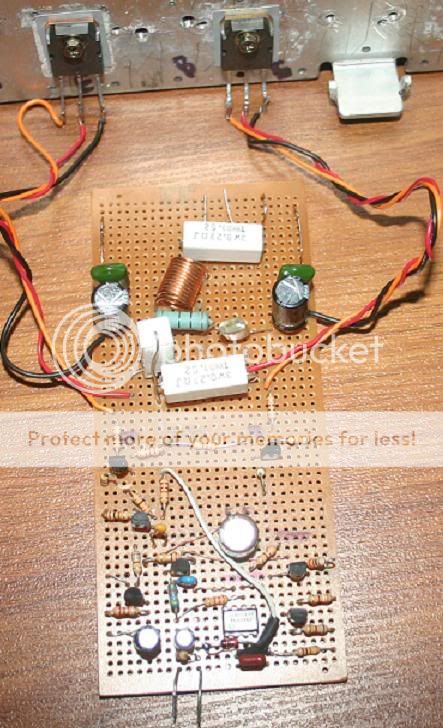
here is the Mooly amp circuit
Hi mooly,
This Vro-board for test purpose.
I have just semi finished mooly amp. It is pro type circuit haven’t check yet. Just finished parts lying. There are C5 and C8 still not yet fix due polarity confused. Any way now I know it is actually 10uf. And R8 we can use from 470. Later on I will finish this part.
Here is the circuit on vro aboard.
Later on I need test measurements info from mooly.
Best regards.
michael
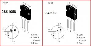
mooly, i think i need to mske sure for mosfets connection. here can't read properly too small font.
---------------------------------
2sk1058 on the -v rail
G = goes to R21
D= goes to -v rail
S= goes to R24
-----------------------------------
2sj162 on the + rail
G = goes to R18
D= goes to +v rail
S= goes to R23
--------------------------
is this correct connection?
---------------------------------
2sk1058 on the -v rail
G = goes to R21
D= goes to -v rail
S= goes to R24
-----------------------------------
2sj162 on the + rail
G = goes to R18
D= goes to +v rail
S= goes to R23
--------------------------
is this correct connection?
Hi Space,
That was quick First things first. Before you switch on disconnect ALL 6 wires that go to the FET's. You can power it all up without these connected, make sure nothing is connected to the input and output lines.
Connections to the FET's. The 2SJ162 is the "top" one that goes to the positive rail. The SOURCE goes to the +45 volt rail and the DRAIN is the output that goes to the 0.22 ohm. The 2SK1058 is the "bottom" one and again DRAIN is the output and SOURCE to - 45 volts. The 270 ohms that go to the gates, these MUST be placed on the pins of the FET's VERY IMPORTANT. Also don't have all those wires twisted together keep them separate and short.
With the FET's NOT CONNECTED, power it up and check that the output is at ZERO volts DC. Check that there is 12 volts across pins 4 and 7 of the IC and that there is about 0.7 volts across R5 the 100 ohm. I can't see a preset (R8) in your picture. You MUST use a pot to begin with. If you have no pot then for now short it out, that is link collector Q5 and collector Q3. DONT use a fixed 470 ohm.
That was quick
First things first. Before you switch on disconnect ALL 6 wires that go to the FET's. You can power it all up without these connected, make sure nothing is connected to the input and output lines.Connections to the FET's. The 2SJ162 is the "top" one that goes to the positive rail. The SOURCE goes to the +45 volt rail and the DRAIN is the output that goes to the 0.22 ohm. The 2SK1058 is the "bottom" one and again DRAIN is the output and SOURCE to - 45 volts. The 270 ohms that go to the gates, these MUST be placed on the pins of the FET's VERY IMPORTANT. Also don't have all those wires twisted together keep them separate and short.
With the FET's NOT CONNECTED, power it up and check that the output is at ZERO volts DC. Check that there is 12 volts across pins 4 and 7 of the IC and that there is about 0.7 volts across R5 the 100 ohm. I can't see a preset (R8) in your picture. You MUST use a pot to begin with. If you have no pot then for now short it out, that is link collector Q5 and collector Q3. DONT use a fixed 470 ohm.
Attachments
hi mooly,
update.
without connect mosfet there is 0 voltage on output but when i attach mosfets there showing high voltage like 16v. its some where got bugs definetly (human error).
i am not using high voltage for now. i am using only 24vdc for testing perpose. should i use only 12v for testing? still need to find where is the bugs......have to check the circuit was properly build. let you know tomorrow. i checked TL071 4-7pin have 12v.
i also plcd R8 pot and adjusted 470ohms.
thank you.
michael
Hi Space,
Sounds like you are nearly there. I will be away most of tomorrow from about 8.30AM, so here are a few things to check.
First make sure the pot is set to zero ohms, not 470. It must read dead short from collector Q3 to collector Q5.
You need at least -/+ 20 volts or so even for testing, but with the outputs disconnected nothing will go pop.
1. Run it up without the FET's connected-- all 6 wires disconnected.
2. Confirm pin 7 of IC is connected to ground.
Confirm pin 4 is at -12 volts --- if you are using a low supply voltage you may need to drop R27 the 10 K feeding the zener to around 5K6 but only do this if the 12 Volts is low.
3. Confirm the output is at Zero volts to within a few millivolts.
4. Confirm that there is 0.6 to 0.7 volts across R5. This will show the current source Q2 and Q3 are working correctly.
5. If that is OK read on DC volts across R17. If you now adjust the pot the voltage across R17 will vary going from zero to perhaps 6 or 7 volts or so. The voltage across R22 should vary in the same way but the two readings will not be equal until the outputs are connected.
If all that is OK then all that remains is to connect the outputs but first set the pot back to ZERO again so there is no voltage across R17 and R22.
Refer to the picture I posted for the pin outs. The 2SJ162 is the top one connected to the positive rail. The 270 ohm gate resistors must go on the FET itself, not on the PCB. The source which is the middle leg goes to the positive rail. The drain goes to the 0.22 ohm.
Do the same for the 2SK1058. Again the middle leg goes to the negative rail and the drain to the other 0.22 ohm.
update making amp
hi mooly,
Today i have tried again. i think i am very near to getting proper volage at output. it's now showing 5.67v on output, there is some were can be error. so i need to check even more details. voltage at +rail are very good, showing 0v. only have problem on -rail which is showing 0.200v, as i know it should be 0v. its responding the input only problem is high voltage at output. i will let you know update.
thank you for your help.
best regards
michael
update again
hi mooly,
finally i can hear the sound of your amp. great sound.
ok, there are still a bit problem when i make the pot to 0v then R17 showing 0vlt too but R22 showing 200mv. when i connect the input there are no more showing this voltage on R22 and output gets under 0v too...anyway now it is working fine on my 24vdc.
sound quality can't tell right now as it is on low voltage.
trble is nice but the vocal is a bit rough not so sweet as it should be. very musical.
i think you are now online...
thank you.
micahel
- Home
- Amplifiers
- Solid State
- My MOSFET amplifier designed for music