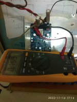
Farther process,testing using +/-35v.
Two 18R/10W resistors instead of fuses.
Input shorted.
Out is open,no load.
Underbiased. 159mV throu 18ohm/10w.
Offset =5mV I think because Vzener=10v still not 12v.
Amplifier is rock stable again!
Two 18R/10W resistors instead of fuses.
Input shorted.
Out is open,no load.
Underbiased. 159mV throu 18ohm/10w.
Offset =5mV I think because Vzener=10v still not 12v.
Amplifier is rock stable again!
Attachments
Last edited:
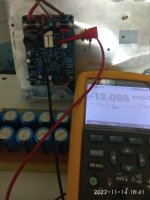
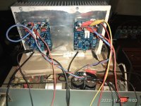
+/-35v,no protective resistors,fuses in situ.
Bias adjusted for 13mV/0.22ohm=0.059A or 59mA.
Still no smoke,no smell.
I think that is time for cheap speakers connection.
I will connect in series with 10.000uf cap.Yes i will try to keep cheap speakers safe for other amplifiers checking!
Next step,using a pair of more expencive speakers....with caps again.
Finall step,+/-45v.
Stay tuned!
Attachments
Last edited:
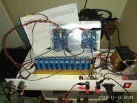
So all still looking good...Still no smoke,no smell.
You're worse than meI will connect in series with 10.000uf cap.

Yes,I don't afford more destroyed speakers.💣So all still looking good...
You're worse than me
Singing in stereo!
Please do not ask for impressions,wait the for the next step😉
Attachments
Last edited:
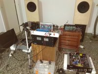
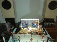
I want to push this a little harder..💣
Connected with better speakers(caps in series of course)
Ok man,I think that I can stamp this as ..TESTED!
Up to now is absolutely stable,no surprises,no smoke no smell no heat,only lovely dynamic music.
To be continued 🤣
Connected with better speakers(caps in series of course)
Ok man,I think that I can stamp this as ..TESTED!
Up to now is absolutely stable,no surprises,no smoke no smell no heat,only lovely dynamic music.
To be continued 🤣
Attachments
Up to now is absolutely stable,no surprises,no smoke no smell no heat,only lovely dynamic music.
Well that is good
To be continued
Could be a long wait because you'll probably just want to keep listening to it......
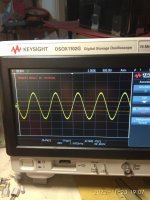
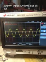
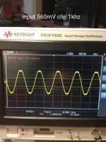
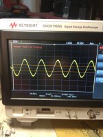
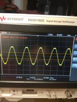
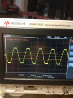
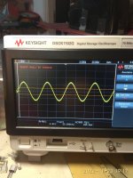
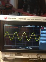
Final test.+/-45v.
Yes,it is rock stable again.
I want to mention that it isn't a good option to use a lower voltage power supply than +/-45v.
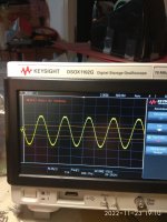
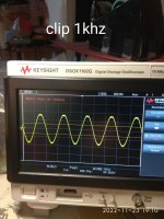
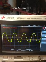
If you will use a lower voltage like +/-35v you will expect high distortion playing near to clip levels.
Yes,it is rock stable again.
I want to mention that it isn't a good option to use a lower voltage power supply than +/-45v.
If you will use a lower voltage like +/-35v you will expect high distortion playing near to clip levels.
Attachments
Last edited:
+/-45v bias100mA
Attachments
-
 IMG_20221123_191013.jpg381.3 KB · Views: 77
 -
 IMG_20221123_191107.jpg388.7 KB · Views: 55
 -
 IMG_20221123_191158.jpg387.2 KB · Views: 50
 -
 IMG_20221123_191158.jpg387.2 KB · Views: 52
 -
 IMG_20221123_191320.jpg397.6 KB · Views: 54
 -
 IMG_20221123_191440.jpg387.1 KB · Views: 52
 -
 IMG_20221123_191609.jpg408 KB · Views: 59
 -
 IMG_20221123_191621.jpg390.1 KB · Views: 59
 -
 IMG_20221123_191732.jpg375.6 KB · Views: 59
 -
 IMG_20221123_191833.jpg338.7 KB · Views: 86
 -
 IMG_20221123_192000.jpg358.4 KB · Views: 79
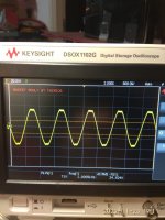
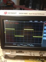
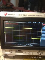
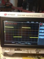
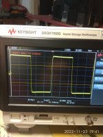
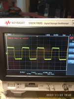
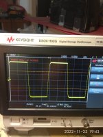
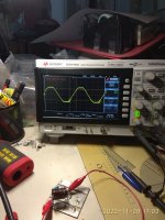
Square wave
Attachments
-
 IMG_20221123_192059.jpg401.4 KB · Views: 65
 -
 IMG_20221123_192137.jpg353.5 KB · Views: 51
 -
 IMG_20221123_192203.jpg364.2 KB · Views: 50
 -
 IMG_20221123_192226.jpg363.1 KB · Views: 59
 -
 IMG_20221123_192335.jpg391.1 KB · Views: 58
 -
 IMG_20221123_194135.jpg399.1 KB · Views: 55
 -
 IMG_20221123_194217.jpg379 KB · Views: 66
 -
 IMG_20221123_194340.jpg386.2 KB · Views: 66
Hi Mooly next will become THD measurements.That's all looking good to me. What's next? trying it on your main speakers?
I like a complete test!
In the meantime I will prepare new speakers.
The Asathor published here in DIY.
https://www.diyaudio.com/community/threads/asathor-a-jbl-4367-clone.367215/page-20#post-7175826
Last edited:
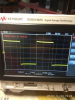
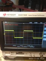
Hi salas,this is my question too.Is that negative base edge oscillation in #1,313 last picture (input 560mV clip) normally expected?
In any case I must clarify that I need to repeat this measurement connecting a thiele circuit .
I have to repeat this measurement because no thiele circuit was used.
Attachments
- Home
- Amplifiers
- Solid State
- My MOSFET amplifier designed for music