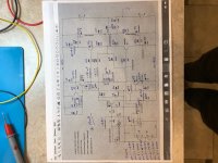
schematic with my actual voltages
I have not tried any ferrite beads before, but with no one else in this thread needing them to get their am to be stable, I don't think that is the answer.
I went through the Spice file that Mooly posted with voltages - I did update all the numbering to match my as-built schematic 2.2.1 and noted my actual voltages in BLUE.
Looks like the only voltage difference is with the TL071 pin 6. I get -4.78V and Mooly has -5.62V. Otherwise it seems to be very similar.
Attachments
Stability issues would have been the very last kind of problem you should be seeing with this amp.
Make sure you have no load connected when checking bias. Lets just rule that out out for a start.
Your voltages look fine. I'm assuming the output node is extremely close to zero volts.
Is the bias altering quickly? or is it just slowly drifting around?
An oscilloscope on the output would show if there were any genuine oscillation or whether this is something totally different.
The TL071 output pin voltage will vary slightly build to build because of differences in transistor gain at the front end. Different devices will need more or less base current pulled through the 33k to achieve the correct bias.
Your looks fine. The critical DC conditions are that the output is at zero volts DC, that the opamp output is not to close to either -12v or 0v which would meant the servo is out of range, and finally that the current in the VAS stage is around 6ma.
Yours looks good on all counts.
Other thoughts. Make sure the 1 ohm test resistors really are 1 ohm and not something higher.
Thanks for replying Mooly
Testing criteria:
I have never had a load on the speaker output
I have tried it with the input shorted and not shorted (same result)
The bias is kind of surging - granted I am using a 150W DBT
- once the bias reaches close to 150mA, it will surge to 500mA, then back to 130, and just continue up and down. Generally max's out at 650mA.
DC offset is good and only varies +/-1mV
I did measure the in-line supply resistors and were 0.9r and 1.0r with a Fluke meter
One thing I tried last night, was to turn up the bias until it began to surge. Then I touched the components to see if anything was getting hot, only T7 was getting warm, all else was cold.
I tried some freeze spray and the only noticed that T1 would lower bias until it warmed up again.
Then I touched the tops of the caps to see if they were getting hot - touching either C6 or C3 would reduce the bias and taking my finger off the bias would go back up immediately. Tried this 4-5 times and the same result. High bias, touch top of C6 or C3 and bias would decrease to 15-20mA take finger off and bias would rise again.
Also took the Mosfets out and tested just the front-end. Only voltage that was off was on the 270R gate resistor (R30), it had 18.4V, but when I have the outputs in it is close to rail voltage of 40V.
I have a scope, however not very good with it yet, so I have not hooked it up in fear of shorting something.
I forgot to mention, some of the resistors are slightly different values, but very close.
100r - I used 102r (R5)
22k - I used 22.1k (R1, R4, R14)
220r - I used 221r (R19, R20)
Didn't think about it earlier, because these small variances have not made a difference in the 4 other amps I have built. But I don't want to leave anything unknown to try to find the issue.
100r - I used 102r (R5)
22k - I used 22.1k (R1, R4, R14)
220r - I used 221r (R19, R20)
Didn't think about it earlier, because these small variances have not made a difference in the 4 other amps I have built. But I don't want to leave anything unknown to try to find the issue.
I think you need to look with the scope.
Touching any parts like you mention and seeing the bias alter is a sure sign of instability and that comes as a real surprise because the single ended front end topology is super stable and very tolerant of even things like poor layout.
The resistor differences will have no effect on fault.
To use the scope (is it a 'proper' one or a USB one or something in between). You wont do any damage as long as you follow some basic steps. Firstly make sure that you connect the scope probe ground lead to the main zero volt point of the power supply. That is the common point between the two reservoir caps in the power supply.
With the scope input AC coupled and the volts/div set to high value initially connect the probe tip to the main amplifier output which is the junction of the two 0.22 ohm resistors.
You should see a straight line on the scope. Oscillation will show as the trace becoming thick and blurred. You may have lots of unwanted signal there, many volts AC.
So that's the first step.
Also have you got the Zobel network correctly connected. That is the 0.1uF cap and 10 ohm resistor at the output. Make sure the values are correct.
Touching any parts like you mention and seeing the bias alter is a sure sign of instability and that comes as a real surprise because the single ended front end topology is super stable and very tolerant of even things like poor layout.
The resistor differences will have no effect on fault.
To use the scope (is it a 'proper' one
or a USB one or something in between). You wont do any damage as long as you follow some basic steps. Firstly make sure that you connect the scope probe ground lead to the main zero volt point of the power supply. That is the common point between the two reservoir caps in the power supply.With the scope input AC coupled and the volts/div set to high value initially connect the probe tip to the main amplifier output which is the junction of the two 0.22 ohm resistors.
You should see a straight line on the scope. Oscillation will show as the trace becoming thick and blurred. You may have lots of unwanted signal there, many volts AC.
So that's the first step.
Also have you got the Zobel network correctly connected. That is the 0.1uF cap and 10 ohm resistor at the output. Make sure the values are correct.
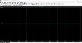
This is how oscillation could look on a scope. I've rigged the simulation of the amp be unstable.
The first image is no oscillation. The scope shows no signal present and the trace just shows a straight line.
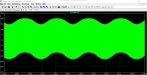
The second image shows oscillation. The timebase speed is quite slow and so it shows as a thick blur with no detail. Look at the voltage scale at the left.
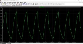
If the timebase is expanded (time per division) then we can see the signal in detail. The frequency is around 1.7 megahertz and so it depends on the scope bandwidth as to whether it will show that. The frequency could be lower or much much higher.
As a practical point, if the amplitude of any oscillation were very large then the 10 ohm in the Zobel network would be getting very hot... and I assume it is not.
The first image is no oscillation. The scope shows no signal present and the trace just shows a straight line.
The second image shows oscillation. The timebase speed is quite slow and so it shows as a thick blur with no detail. Look at the voltage scale at the left.
If the timebase is expanded (time per division) then we can see the signal in detail. The frequency is around 1.7 megahertz and so it depends on the scope bandwidth as to whether it will show that. The frequency could be lower or much much higher.
As a practical point, if the amplitude of any oscillation were very large then the 10 ohm in the Zobel network would be getting very hot... and I assume it is not.
Attachments
Thanks for the walk through. I have confirmed with the oscilloscope and a heating up 10r zobel resistor that it is indeed oscillating. Think we already knew that - lol.
I have re-flowed all solder joints, rechecked everything at this point and I can’t find anything “wrong” with the voltage measurements or parts.
I’m at a loss at this point. Not sure how to narrow the oscillation down. Strange that even after the zobel was heating up, the heatsink was barely warm? And none of the small-signal to-92s are getting warm either.
Last edited:
I have not tried any ferrite beads before ..
Sorry bullittsang -- I didn't mean to suggest a solution, only a diagnostic indicator. As DIY'ers we often underestimate the lot-to-lot variations in semiconductors, and the effect of those on circuit behavior. FET's are particularly rude that way.
It doesn't mean there's anything wrong with the design, just that with this board layout, and these particular active devices, an unexpected behavior results.
BTW, I couldn't find R30 (mentioned in #1084) in the image on post #1082.
Any chance your 10R Zobel resistor is a wirewound type?
Regards
edit: What frequency and approximate amplitude is the oscillation at the output?
Last edited:
Keep bringing the suggestions - I will try most anything at this point.
R38 (oops not R30-bad eyesight) is the 270R gate resistor for the J162.
The 10r is a 2W wirewound - do you think that could cause this? I may have put the wrong resistor, because I have Metal Oxide resistors in my build box too? Hmmmmmm.
I am not very good with the o-scope yet, but it went back and forth showing 1.2MHz and 12.4MHz and showed peak to peak of 1.4V? The zobel did not heat up, until (possibly wrong - go easy on me), but I input a signal of 1k to see how bad the oscillation was. Zobel didn't get hot until the signal was 4.1V peak to peak output. Only ran test until zobel (R25) got hot, then turned it off, so I don't think it caused any issue.
Still does the same thing - no constant bias, no change after all these tests.
So I pulled the 680k FB resistor (R9) and the 150pF capacitor (C2) and the same behaviour - no change.
EDIT - any thoughts on replacing the 22pF (C7) with either a 4.7pF or 47pF? I have both on hand, maybe that would push down the oscillation? No idea myself.
Last edited:
I sure feel ya' on the bad eyesight ..
And on the 'possibly wrong ..' -- no need to go easy on you! That's actually a useful indicator, too: *Does a strong signal swamp the oscillation, or just give it a nice roller coaster ride?*
Having two frequencies a decade apart does sure add some excitement ..
If it was me, I'd consider tacking that 4,7pF B-C across T5, or even T4-T5, and leave C7 alone for now. But my money is on the Sziklai (am I spelling that right?) pairs -- there's a lot of bandwidth potential there and it could vary almost a couple orders of magnitude over different devices with the same part number.
But, will await results and defer to the wiser minds here.
Cheers
Last edited:
They are both AVIVE!!!! Changed out the 10r 2W wirewound resistors in the zobel network (R25) with 10r 3W Metal Oxide and the oscillation is gone.
Changed the resistor in the other channel (same issue) and now it is working as well.
Getting late, so I have only been idling them for about 30 mins, at 200mA (2-pair of outputs) and they are stable to within +/-5mV.
Thanks Ian and Rick - without your observations and suggestions, I would not have thought the "kind" of resistor would have made that big of a difference, nor caused oscillations on this amplifier. Thanks again - the knowledge and generosity of those on this forum always amaze (and humble) me!
Try and get it finished up and I'll post some pictures of the final product and some listening impressions.

Great to know you managed to get it working, and success after a bit of struggle gives greater satisfaction for the efforts put in..
Thanks to Ian and Rick for pointing out the cause.
Mooly had probably foreseen this issue and his post #1 schematic specifically mentions this.
Yes, would be interested to hear your music impressions.
Thanks to Ian and Rick for pointing out the cause.
Mooly had probably foreseen this issue and his post #1 schematic specifically mentions this.
Yes, would be interested to hear your music impressions.
That is great news, and thanks to Rick for mentioning to check the resistor type. It is often stated that such parts must be non inductive and of course that is correct. Same applies to such things as the 0.22 ohms and in BJT designs, the 'emitter resistors' and yet designers like Doug Self actually say (and I have his third edition book on power amp design in front of me) that for Zobel networks it seems not to matter. Hmmm
The big difference here though is that this amp uses much much faster output devices than the bjt's in the book.
Make sure any bits you removed (caps etc) are put back... it is easy to forget sometimes.
Excellent news Enjoy.
The big difference here though is that this amp uses much much faster output devices than the bjt's in the book.
Make sure any bits you removed (caps etc) are put back... it is easy to forget sometimes.
Excellent news
Enjoy.Try and get it finished up and I'll post some pictures of the final product and some listening impressions.
One more thing , pl add the 6uH inductor inline with output as per schematic when you finalize the build..
- Home
- Amplifiers
- Solid State
- My MOSFET amplifier designed for music