When I get back home I will pull the servo and see what happens. I don't see any fuzz on the scope. This is and older design but a friend recommended it to me so I said I would give it a try.I didn't read every post so I guess I need look more closely.it's possible that mooly isn't even following the thread any longer.
Blessings , Terry
Blessings , Terry
The biggest issue is the offset.
What opamp do you use? Note that the input emitter is negative (around -5V IIRC) and that's why the feedback capacitor orientation is uncommon (positive side towards ground).
Mooly will be here as he's an active administrator.
I used TL071. I'm wondering if it is being over loaded. I noticed the last time I tried running it that it was sort of tame running through the light bulb and variac. However, I was unable to raise the bias through the light bulb so I plugged in direct. That raised the rail to +-47V and the offset started bouncing. I'm thinking that maybe that raised the current too much in the front end or something. When I get a chance I'm going to try running it at lower voltage and see what happens. I want to be able to run higher rails, otherwise why bother using two pair of outputs.
Thanks, Terry
Thanks, Terry
I had a few minutes so I tried running at different rail voltages. No dice. The offset continually bounces all over the place. For some reason the servo is is having trouble settling. This is the first time I've seen a servo with just a single zener. Is it possible that the servo just needs more voltage/current? Isn't -12v-0v the same as +-6V?
it's possible that mooly isn't even following the thread any longer.
Blessings , Terry
I'm still here. It was the middle of the night when you posted all this
")
Well I have it singing but it is not a very happy camper. I will have to do some more reading through the thread. I built it to the schematic in post #1 and the values on Alex's board which seem to match. The output doesn't look too bad with a load attached. A little over shoot on the square wave. The biggest issue is the offset. Once I play a sine wave through it the offset starts jumping all over the place and doesn't settle again unless I shut it down and restart. Any suggestions are welcome.
Also, the gains seems really low. With a 1.2v input I am only getting about 8.5V output.
Blessings, Terry
There has to be a significant error in the build because the gain is actually very high on this design... numerically around '47'. That's the biggest clue as to where your problem lie.
I used TL071. I'm wondering if it is being over loaded. I noticed the last time I tried running it that it was sort of tame running through the light bulb and variac. However, I was unable to raise the bias through the light bulb so I plugged in direct. That raised the rail to +-47V and the offset started bouncing. I'm thinking that maybe that raised the current too much in the front end or something. When I get a chance I'm going to try running it at lower voltage and see what happens. I want to be able to run higher rails, otherwise why bother using two pair of outputs.
Thanks, Terry
The servo must use a genuine TL071 to operate correctly on its single rail. As long as that is so then there should be no issue there. The output of the servo should be around -6 volts. So check that, it might give a clue. If the servo feedback were missing or open (or the 1meg was incorrect and say 1k) you could get weird effects and both effect gain and the servo action.
Thanks for replying. I followed the values on Alex's silk. I have looked it over and don't see any glaring errors but I will look again. Both boards are doing the same thing so the error has to be on both. Do you know if any amps have been built using this layout?
Thanks, Terry
Thanks, Terry
I can't recall any that have used Alex's layout but I have a vague recollection of an error on one of the patterns (which I think was pointed out at the time).
I'll look back in the thread. Check the DC voltages around the servo though. You need to be seeing around -6 on the opamp output.
I'll look back in the thread. Check the DC voltages around the servo though. You need to be seeing around -6 on the opamp output.
Which board layout are you using and I'll take a look too.
I'm using the files from post #300 that was recommended in post #1.
I just went over the board and compared it to the schematic in post #1 and the only thing I see different is that on the schematic, C12 and C13 are 220u and on the board C12 is 100U. I can't see how that can affect gain. Looks like I'm going to have to mark up some voltages.
They are just rail decoupling. The gain is set by the ratio of R14 and R7 (22k and 470 ohm).
Start by checking the servo output and see what DC voltage you have on pin 6. Also check the minus 12 volts on pin 4 is OK.
I'll take a look at the board layout later. Whatever the problem is, it can't be much.
Start by checking the servo output and see what DC voltage you have on pin 6. Also check the minus 12 volts on pin 4 is OK.
I'll take a look at the board layout later. Whatever the problem is, it can't be much.
Nothing jumps at as an error at a first look at the board.
The vital checks (with NO load and NO signal) are,
1/ Servo supply voltage at minus 12 volts.
2/ Servo output should be clean and steady at around minus 6 volts.
3/ Voltage across R5 (100 ohm) should be around 650 millivolts. This gives a current of approx 6 to 7 milliamps through the bias preset.
Make sure the 0.1uf across pins 2 and 6 of the opamp is correct. If that was open circuit or the print open or damaged then you could get all kinds of problems.
Make sure that the feedback cap C3 is fitted with correct polarity. Negative end to Q1 emitter.
This shows the typical voltages on a -/+45 volt rail.
Attachments
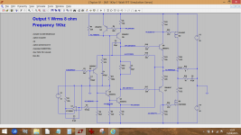
-11.99Nothing jumps at as an error at a first look at the board.
The vital checks (with NO load and NO signal) are,
1/ Servo supply voltage at minus 12 volts.
-10.522/ Servo output should be clean and steady at around minus 6 volts.
.605V3/ Voltage across R5 (100 ohm) should be around 650 millivolts. This gives a current of approx 6 to 7 milliamps through the bias preset.
checkMake sure the 0.1uf across pins 2 and 6 of the opamp is correct. If that was open circuit or the print open or damaged then you could get all kinds of problems.
checkMake sure that the feedback cap C3 is fitted with correct polarity. Negative end to Q1 emitter.
This shows the typical voltages on a -/+45 volt rail.
I have found one issue though I don't know why. Q3 (Q5 above) has zero vbe. Base and emitter are both 43.7V. The transistor tests fine. Q2 (Q4 above) has .5V vbe.
Both boards measure the same.
I'm attaching an asc file that I think is the same as the circuit I am using but it doesn't work either. Can you take a look and see if you can make it work?
Thanks, Terry
Attachments
Last edited:
+Have you tried 22pf across the gate and source on the 2sk1058.s . Evette
Not yet. I need to get the voltages right first.
I added the 22p to the G-S 1058. No change. I just checked and I was wrong. Q3 ;has .658 vbe so plenty but for some reason when I measured earlier the b and e both measured the same to ground. I just took some more measurements and a couple things of note. When I first power up I see about 30mV offset at the output. it takes about 10 seconds or so for it to rise to more than a few volts. It is like a cap is loading and pulling it off.
One more thing as I am trying to learn something here. Should this circuit work without the IC in place? My understanding is that it is there to correct a small offset. If I pull the IC I have 10V offset and after a few minutes it may rise to twice that much.
Thanks, Terry
One more thing as I am trying to learn something here. Should this circuit work without the IC in place? My understanding is that it is there to correct a small offset. If I pull the IC I have 10V offset and after a few minutes it may rise to twice that much.
Thanks, Terry
Solved it!!!!!
I had to reverse C3, the 470uF cap on the NFB. The schematic and board silk have it with the + lead to ground. In an effort solve this I looked through a bunch of schematics from other amps I have built. Every one of them with this type of NFB had the - lead to ground. I figured there was so little voltage there it wouldn't hurt to try reversing it. So I reversed it so that the - lead is to ground and now all is beautiful. It has been playing music for 30 minutes or more and everything is stable. I ran some square waves through it as well and they look real nice. I'm going to let it burn in for a while on my test speakers and then I'll hook it up to the A/B setup and compare it to a few other amps.
I also discovered why I thought the gain was low. I had inadvertently switched my tone generator to sinc mode and it lowered the output to 300mV so I only thought I was inputting 1.2V. It has plenty of gain and sounds sweet.
More later.
Blessings, Terry
- Home
- Amplifiers
- Solid State
- My MOSFET amplifier designed for music