Thanks mjona, for digging out the PDFs. I don't think I have read the article in a few years now. I'm sure that issue will be around somewhere in my boxes of publications though.
An interesting feature of Rod's retro designs with their bootstrapped VAS and simple LTP without current mirror, is they sound surprisingly good as they are. The SC power amplifier alone, is obviously more refined in Douglas Self's style and has no perceptible distortion, just an eerie lack of sound character that is not always to my liking for personal listening. That's been a source of disapointment because the kit of parts was not cheap for a 20W integrated amp. I later sold mine but still have a second that I built for demonstrating low THD to a few skeptical friends.
An interesting feature of Rod's retro designs with their bootstrapped VAS and simple LTP without current mirror, is they sound surprisingly good as they are. The SC power amplifier alone, is obviously more refined in Douglas Self's style and has no perceptible distortion, just an eerie lack of sound character that is not always to my liking for personal listening. That's been a source of disapointment because the kit of parts was not cheap for a 20W integrated amp. I later sold mine but still have a second that I built for demonstrating low THD to a few skeptical friends.
The Self amp is an intellectual feat of high loop gain, paragon of stability, and benchmark of low THD. But in pursuing low THD, oddly the sound becomes sterile.
A 'badly' designed amp, with resistor supply to LTP, single VAS driven from a single LTP side with resistor, no current mirror, and bootstrap VAS sounds better.
I have given up trying to explain why this happens; the reason is not so much the engineering, which is all over after the shouting decades ago, but the psychoacoustics.
But this stuff is not interesting for techo minds!
This forum has delivered some wonderful amps over the years, in recent times from Valery Vaichenko and Ranchu32.
Maybe we should be detectives, not engineers?
Hugh
The Self amp is an intellectual feat of high loop gain, paragon of stability, and benchmark of low THD. But in pursuing low THD, oddly the sound becomes sterile.
A 'badly' designed amp, with resistor supply to LTP, single VAS driven from a single LTP side with resistor, no current mirror, and bootstrap VAS sounds better.
I have given up trying to explain why this happens; the reason is not so much the engineering, which is all over after the shouting decades ago, but the psychoacoustics.
But this stuff is not interesting for techo minds!
This forum has delivered some wonderful amps over the years, in recent times from Valery Vaichenko and Ranchu32.
Maybe we should be detectives, not engineers?
Hugh
One point to consider would be the reverse bias diodes across the feedback decoupling capacitor to protect this from a negative d.c. being applied due to some circuit failure.
The theory is the a.c. signal through the capacitor is lower than the diode conduction threshold and therefore out of circuit.
However the lower feedback decoupling arm is in effect a grounded input to an inverting amplifier and any signals generated within this arm are not subject to feedback correction.
At a micro level there is a question of whether there is any significant interaction between the a.c. signal and the charges in the material of the K end of D1.
Electrons are more mobile than holes so what is removed and what is put back and what are the phase relationships with increasing frequency.
If no-one has had reliability problems are these diodes really necessary.
Thanks mjona, for digging out the PDFs. I don't think I have read the article in a few years now. I'm sure that issue will be around somewhere in my boxes of publications though.
An interesting feature of Rod's retro designs with their bootstrapped VAS and simple LTP without current mirror, is they sound surprisingly good as they are.
I experienced my own surprise fairly recently listening to a 70's Kenwood amplifier someone had gifted to my brother.
It had a brief burst of dc/hum noise at switch on so I took it home to sort this and anything else - capacitors/dry joints etc.
This amplifier uses the circuits you describe. A point of difference is the Kenwood output stage has short circuit protection.
They don''t seem to be used or even discussed much. The first time I saw them was in the late Randy Slone's power amplifier construction manual, in which he acknowledged the idea was from Self, around 25 years ago. I haven't identified any issues with this problem in my own amplifiers but I've had to repair a few that obviously did. These were PA, stage amps and also a few large high-end amplifiers, where you expect unusual problems since high voltage breakdowns can cause sometimes baffling collateral failures......If no-one has had reliability problems are these diodes really necessary.
When one side of the output stage fails, a chain of events can induce the other side to follow but at some point, one rail voltage will probably appear at the output node and so a DC voltage of up to Vrail/gain will appear across the feedback cap. With only 22V rails and using a 10-25V cap, you could say this would be a non-issue. However, if you had a large, say 250W class AB amplifier using tightly budgeted voltage ratings, those diodes could be essential, whatever the cost to performance.
Perhaps using a different diode type - maybe a Schottky, though it still has N type silicon for a Cathode, could be located at the end of the diode chain. It might be interesting to look for any changes in an FFT plot of the amplifier output but simulation could also make use of any properties you were able to model.
I have tried this, double diodes across the shunt cap in the fb divider, and I have never noticed ANY sound quality issues at all. Any AC through the cap is at very low impedance, and in any case these diodes are not biased since the DC on these points is little more than 150mV, always less to even hit the start of the IV curve on the diode.
Actually, for all my comments of the Self approach I do not criticise this idea. I think it's pretty good as it protects the fb transistor and shunt cap in the event the output goes south (or north!). In truth you can put in a 4.7V zener here too, just one...... it will strike at +4.7V or -0.6V and it's one diode, not two.
Cheers,
Hugh
I have tried this, double diodes across the shunt cap in the fb divider, and I have never noticed ANY sound quality issues at all. Any AC through the cap is at very low impedance, and in any case these diodes are not biased since the DC on these points is little more than 150mV, always less to even hit the start of the IV curve on the diode.
Actually, for all my comments of the Self approach I do not criticise this idea. I think it's pretty good as it protects the fb transistor and shunt cap in the event the output goes south (or north!). In truth you can put in a 4.7V zener here too, just one...... it will strike at +4.7V or -0.6V and it's one diode, not two.
Cheers,
Hugh
There are a couple of changes from Self's Blameless Amplifier circuit.
Many capacitor and resistor values are the same and the main points of difference are the CFP output stage, the Thiele stability network, the substitution of Q6 for two series diodes in the CCS, and adding an extra diode in parallel with the 220 uF feedback decoupling capacitor.
This basic structure has been carried forward into the Ultra-LD 200 watt series of amplifiers and still seen in a modified form in the Mk4 version published in July, August and September 2015.
Some of the modifications have been published so owners of earlier versions can up-date their amplifiers that has not been the case with the 20 watt Class A circuit.
The Mk4 Ultra-LD has been touted as better than the latter - the double diode across the feedback electrolytic capacitor (increased in value from 220uF to1000 uF) remains.
Two things stand out with this - there is a ferrite bead in series with the input and the Thiele coil (fine tuned value) is oriented in a vertical plane and standing clear of the board.
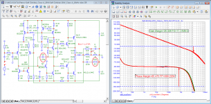
Albeit that Class A amplifier should not generate switching artifacts it still has a -3dB frequency of 190 kHz.
However, let's also consider variations to Silicon Chip's 20W amplifier, which is virtually Self's blameless CFP topology.
This type is often referred to as a "high bias" design as there is little to distinguish it from a class AB design apart from the bias current, feedback resistors and rail voltages. Miller compensation in the VAS at least, usually remains unchanged from class AB to A operation. We can fit 30MHz output devices and whip up the rail voltages and feedback ratio to make a standard blameless amplifier or leave it with +/- 22V rails if we wish to compare apples etc.
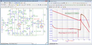
So if we are only reducing the supply rails and the gain to suit lower power operation, how will the risk of instability be increased? Will increased output stage bias alone threaten stability or EMR susceptibility?
Re changing rail voltages.
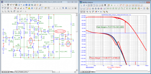
Transistors have a capacitance in the diffusion between the collector and base proportionate inversely to the square root of the applied collector voltage.
The value of this capacitance will increase if the rail voltage is reduced and increase the stability margin. This would have some effect on slew rate.
The reverse applies if the rail voltages are increased - where the 100 pF stability capacitor around the Vas transistor would need to re-assessed.
With a reduction in closed loop gain you would be increasing the frequency point where the change in phase reaches 180 degrees. You would also be pushing the point where the gain declines to unity - disproportionately closer to the 180 degree point and reducing the stability margin.
The Vas stability capacitor is 100 pF in Self's Blameless, and the Silicon Chip 20 watt Class A and mk2 Ultra-LD designs.
That is probably coincidence since the output stages have to be taken into account. I did not find the transistor part designations for the Self Blameless circuit.
FWIW, Self's blameless design was not a commercial product or design, but rather, some variations on a simplified textbook model, low power amplifier design with little variation of components over the years of his articles in WW, E&WW, 6 editions of his handbook, "Self on Audio" editions and the websites........I did not find the transistor part designations for the Self Blameless circuit.
Beginning with the 3rd edition of the handbook to now, I found he adhered generally to the same Motorola/On-semi types and used small-signal types MPSA06/56, Drivers MJE340/350, outputs 2SC3281/2SA1302. As power levels are increased, the small signal types are replaced with MPSA42/92. It seems that in his commercial designs, is where there is actually a lot more variation. Here's one of his 250W Monobloc creations for TAG McLaren: Tag Mclaren 250MR - Manual - Mono Power Amplifier - HiFi Engine
The Signal Transfer Company, which produces kits for his textbook designs, now offers one known as the compact blameless amplifier, the first to actually carry the title.
The Signal Transfer Company: Compact Blameless Power Amplifier
You can make out from the PCB overlay, that the nominated semis haven't changed from MPSA06/56, drivers are still MJE340/350 but the outputs are now Sanken MT200 types, presumably LAPTs 2SC2922/2SA1216 or similar.
FWIW, Self's blameless design was not a commercial product or design, but rather, some variations on a simplified textbook model, low power amplifier design with little variation of components over the years of his articles in WW, E&WW, 6 editions of his handbook, "Self on Audio" editions and the websites.
Beginning with the 3rd edition of the handbook to now, I found he adhered generally to the same Motorola/On-semi types and used small-signal types MPSA06/56, Drivers MJE340/350, outputs 2SC3281/2SA1302. As power levels are increased, the small signal types are replaced with MPSA42/92. It seems that in his commercial designs, is where there is actually a lot more variation. Here's one of his 250W Monobloc creations for TAG McLaren: Tag Mclaren 250MR - Manual - Mono Power Amplifier - HiFi Engine
The Signal Transfer Company, which produces kits for his textbook designs, now offers one known as the compact blameless amplifier, the first to actually carry the title.
The Signal Transfer Company: Compact Blameless Power Amplifier
You can make out from the PCB overlay, that the nominated semis haven't changed from MPSA06/56, drivers are still MJE340/350 but the outputs are now Sanken MT200 types, presumably LAPTs 2SC2922/2SA1216 or similar.
Thanks for the links - things have moved on a lot between the Blameless and the Tag McLaren 250R. I liked that a lot and downloaded both manuals to look into further.
Re use of 2SC3281 and 2SA1302 power output transistors in the Blameless and NJL ThermalTrak equivalents in the Silicon Chip Ultra-LD adaption using higher supply rails - ignoring the networks at the output terminal for either - the Blameless should have the greater stability margin.
The network used in Electronics Australia since the Playmaster twin 25 of 1976 still there in Silicon Chip amplifiers is that by Thiele which is to guarantee unconditional stability with reactive loads.
That is the likely explanation why the 100 pF capacitor seen in the Blameless did not need to be increased in the derivative Ultra-LD mk2.
I mentioned previously that in the mk4 version of the latter series of amplifiers the orientation of the coil was changed. There were two articles on this new amplifier - in the first of these in August 2015 the coil sat flat on the circuit board as usual.
In the September 2015 issue the coil stood vertically on a different circuit board. There is a block section within the article discussing distortion and stability covering the Thiele network including a revision of capacitors and resistors types.
There is more in "Ask Silicon Chip" - "Amplifiers Must Be Fitted With Output Inductors" re: the "Tiny Tim" amplifier published in 2013. That has a compact board with the inductors mounted close together with a tin shield between.
You asked a question about EMR in one of your posts. One suggestion was the electrolytic capacitor in the feedback network was at risk resulting in replacement of a bipolar with a physically smaller polar type.
If you are not happy with the sound of your 20 watt Class A you would have nothing to lose from a "look see".
Apart from making up a new coil, fitting a different capacitor and resistors you could try making a shield of non-ferrous material and earthed to fit over the electrolytic feedback capacitor.
Last edited:
Re changing rail voltages.
Transistors have a capacitance in the diffusion between the collector and base proportionate inversely to the square root of the applied collector voltage.
The value of this capacitance will increase if the rail voltage is reduced and increase the stability margin. This would have some effect on slew rate.
As far as comparisons go for Vas stages, BC546 as in the Class A and MPSA06 as in the Blameless may not have the same collector capacitance. The value is not in the datasheet for the latter transistor so there is a caveat in this regard.
Whatever the collector capacitance value is in either case such will be amplified due to the Miller effect and any variation between the two enlarged.
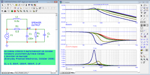
From reading Nicholas Vinen's article on the MkIII version ULD amplifier, I understand that the large (10uH) output coil doubled as an output filter to roll off HF response and ensure better THD figures on test. I don't think any better reason was given for such a high value there. He now reverts to a more usual value of 3uH, lower than Theile's 6.8uH coil, in DIY use as far back as the early 1970s, perhaps before even the twin 25 amp: Vintage Audio Bliss: Playmaster Twin Twenty Five (25) I recall other models with coils wound on F8 ferrite rod too  However, in normal use, core saturation probably wasn't noticeable.
Vinen has made a few radical changes from previous ULD amplifier versions. I think that the vertical coils were more a stylistic change (see Self's builds) from the compact multilayer, bobbin wound coils used for decades and the type specified for the 20W class A amp. Considering the potcore bobbins used are now hard to source, probably a wise decision.
My comments on sound quality are not a technical criticism. I have a subjective POV, which says that some distortion is actually desirable if it is confined to low order harmonics at low levels. I understand you currently use a Nait 5i which would neatly fill that requirement, so I think you will know what I refer to as it applies to all domestic Naim models, even some of the better DIY kit copies now available. However, I don't think you'll ever see Doug Self hailing any Naim product as "blameless"")
I also like a little warmth in the sound for personal enjoyment - I'm not a purist and my experience is that ultra low distortion amplification does not necessarily provide the most satisfying sound - just the cleanest and 'sharpest' which is not to suggest there is anything wrong with it.
However, in normal use, core saturation probably wasn't noticeable.Vinen has made a few radical changes from previous ULD amplifier versions. I think that the vertical coils were more a stylistic change (see Self's builds) from the compact multilayer, bobbin wound coils used for decades and the type specified for the 20W class A amp. Considering the potcore bobbins used are now hard to source, probably a wise decision.
My comments on sound quality are not a technical criticism. I have a subjective POV, which says that some distortion is actually desirable if it is confined to low order harmonics at low levels. I understand you currently use a Nait 5i which would neatly fill that requirement, so I think you will know what I refer to as it applies to all domestic Naim models, even some of the better DIY kit copies now available. However, I don't think you'll ever see Doug Self hailing any Naim product as "blameless"
I also like a little warmth in the sound for personal enjoyment - I'm not a purist and my experience is that ultra low distortion amplification does not necessarily provide the most satisfying sound - just the cleanest and 'sharpest' which is not to suggest there is anything wrong with it.
Last edited:
My Nait 5i is in everyday use being central to my audio and A/V sources. I find it easy to live with.
In my alternative studio and garage I am running a Linsley-Hood Class A 1996 system that I built in that year.
I have built a lot of amplifiers since my early days with the 1969 Class A and the Playmaster Twin 25/40 only to find myself back at square one, unable to escape an addiction.
In my alternative studio and garage I am running a Linsley-Hood Class A 1996 system that I built in that year.
I have built a lot of amplifiers since my early days with the 1969 Class A and the Playmaster Twin 25/40 only to find myself back at square one, unable to escape an addiction.
That seems like a good situation to be in. I wonder what you would make of Rod Elliott's small class A contender, P36 (DOZ). It's also quite simple and low powered - might make an interesting diversion for studio listening.
I would put it on my short list if I could find the time to build it.
There is a lot of house maintenance at home and a beach property that keeps me away from my hobby work and other social activity otherwise now I am in retirement.
Whenever I can get back to hobby work I have two amplifier projects with the electronics ready to go bar the metal work and one for a three way loudspeaker system. I find woodwork easier than metal work so the latter will probably be the first on the list to be finished.
In this form, the scheme is not working.Great amplifier I like it
input signal : 707mV 1khz sinus
Output : 26.5 watt max
Thd : 0.002 %
Gain :25.5 dB
Dc offset : <1mV

Attachments
- Home
- Amplifiers
- Solid State
- Aussies - Silicon Chip 20W Class A Amplifier opinions?