I´m still chewing on my layout for a 6 channel preamplifier with LM4562 (or OPA2134). Forum member KSTR gave me the hint to use a groundplane instead of star ground(s) for signal and power, I tried to develop my own layout. The schema is buffer -> potentiometer -> gainstage. Biasing into Class A is done like written here: http://www.tangentsoft.net/audio/opamp-bias.html The SMD opamp is on the solder side.
The schematic:
Solder side layout per opamp:
And the component side / groundplane layout per opamp:
This the total solder side layout. There are separte ground traces for any pair of opamps connected to the component / groundplane side. On the vertical space between the opamps a 6 channel stepped attenuator will be fitted.
An again the component side / groundplane layout:
Is this the right way of grounding? I´m stuck with this ...?
The schematic:
An externally hosted image should be here but it was not working when we last tested it.
Solder side layout per opamp:
An externally hosted image should be here but it was not working when we last tested it.
And the component side / groundplane layout per opamp:
An externally hosted image should be here but it was not working when we last tested it.
This the total solder side layout. There are separte ground traces for any pair of opamps connected to the component / groundplane side. On the vertical space between the opamps a 6 channel stepped attenuator will be fitted.
An externally hosted image should be here but it was not working when we last tested it.
An again the component side / groundplane layout:
An externally hosted image should be here but it was not working when we last tested it.
Is this the right way of grounding? I´m stuck with this ...?
 Please tell me what´s wrong!
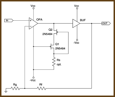
Given the small load currents involved and given the class-A operation (resulting in a benign supply current modulation), one single GND plane is IMHO the easiest and best (that is, don't split it, nowhere). It is more important to split/isolate the supplies, which you did (with the 1R series resistors).
- Klaus
- Klaus
C3 and C4...
are not connected to the top poured ground?
And yes, Class A bias goes to the negative rail, if you choose to use. Curious, spend bucks to get lowest THD on LM4562. Have you seen any THD measurements of the LM4562 in Class A mode? 0.00003% THD+N ain't too shabby.
are not connected to the top poured ground?
And yes, Class A bias goes to the negative rail, if you choose to use. Curious, spend bucks to get lowest THD on LM4562. Have you seen any THD measurements of the LM4562 in Class A mode? 0.00003% THD+N ain't too shabby.
it would be a very strange buffer that didn't have high enough input impedance to leave the op amp output in push-pull Class A with its factory set internal bias
example: BUF634 widebandwith mode Zin = 8 MegaOhm || 8 pF
even 100 uA op amp output stage AB bias current is going to be deep Class A for any V the op amp can swing into such Hi Z
the LM4562 has 5 mA typ per amp to play with and a spec of 13 Ohm open loop Zout - implying lots more than 100 uA output stage bias current already
Alright. I tried to imagine current flow in the groundplane and had the thought the particular opamp pairs otherwise would influence each other. Is it right to place the ground point centered?... one single GND plane is IMHO the easiest and best (that is, don't split it, nowhere)
They are connected to ground in series with the ground connections of C5 / C6.C3, C4 are not connected to the top poured ground?
I absolutely agree with you. If just thought to have the JFET connections as an option and to experiment with different opapms.even 100 uA op amp output stage AB bias current is going to be deep Class A for any V the op amp can swing into such Hi Z
Thank you all!
")
- Status
- This old topic is closed. If you want to reopen this topic, contact a moderator using the "Report Post" button.
- Home
- Amplifiers
- Solid State
- Class A LM4562 (or OPA2134) preamp layout with groundplane