For stuff about the MOSFET amps, I found this:
http://www.eastmarinedrive.com/contents/non-static/audiodgoodman-content.htm
EDIT: Sorry, I notice that was posted earlier - should have read more carefully!
As for the 50W kit, it's all come flooding back
I seem to remember the 50W circuit has a common emitter o/p configuration, which makes it somewhat unusual (I could be wrong, it's so long since I looked)
By way of some reference, thanks to my mate Google:
http://www.soton.ac.uk/~apm3/diyaudio/Maplin_50W.html
No circuit diagram though
Ed
That's it! Eventually, a kind friend of my Dad's made me an aluminium case, which solved a very difficult (and expensive) problem at the time, and provided the perfect heat sink.
Later I upgraded the power supply with two stonking great Elna Cerafine caps and a beefy rectifier. This configuration never looked back and is still a mainstay in the system, some 20 years later.
Been scouring the 'net but can't find any more info. Maplins have become a toy shop and this fine chapter of DIY hi-fi & electronics is retreating rapidly into history... A Maplin shop employee once told me they were "Turning into Tandy"
Cheers,
Ed
![100_3609[1].jpg](/community/data/attachments/131/131161-a53d3f32ad15356478edc6dad1de2b85.jpg)
hi would it be ok if you could send me a copy too many thanks richardI have a copy (scanned) of the page from a 1992 catalogue, it includes the circuit diagram, parts list and set up details. Happy to send you a copy.
Hi, I would like to have a copy of that too.
Thanks and regards,
Vivek.
maplin ampli.
dear sir,
do you have construction manual plz. send me.at khan.shahid251@gmail.com
thanking you
dear sir,
do you have construction manual plz. send me.at khan.shahid251@gmail.com
thanking you
Regarding the 50w, i ran 4 of these in active system. A couple of r's 18/19? were overheating/pcb charred even when the amp was idling, i think the amp was not as stable as others, although i did run them without the o/p ind and probably no zobel.
As for the sound, i thought they were ok at the time, but no reflection other amps ive since used in the same setup proved that these amps lacked clarity.
As for the sound, i thought they were ok at the time, but no reflection other amps ive since used in the same setup proved that these amps lacked clarity.
can any body send me this two items:-
1-THE PCB PHOTO GRAPH OF 1500W AMPLI.USING 10 PIECE TR.MJ 15024& MJ15025 AT OUT PUT TRANSISTOR
2-stachino circuit pcb. AT- khan.shahid251@gmail.com
yours ,masood
1-THE PCB PHOTO GRAPH OF 1500W AMPLI.USING 10 PIECE TR.MJ 15024& MJ15025 AT OUT PUT TRANSISTOR
2-stachino circuit pcb. AT- khan.shahid251@gmail.com
yours ,masood

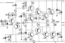
It presents a low impedance path to AC (audio). Without it the junction of R13 and R14 would be modulated with the audio, the emitter of TR5 would "see" 133 ohms" rather than 100 ohm at audio frequencies and the base network of D1/R3 would also be modulated by audio.
Its reason for being included is to increase power supply rejection from noise on the negative rail.
Its reason for being included is to increase power supply rejection from noise on the negative rail.
- Status
- This old topic is closed. If you want to reopen this topic, contact a moderator using the "Report Post" button.
- Home
- Amplifiers
- Solid State
- Maplin 160W (225W) bipolar amplifier design