If you have a digital camera you can send me some detailed pictures. especialy want to hear about your vbias boards...
desolder one, note the value it is set for, now adjust the trimmer all the way to the extremes and tell me the resistance you measure on the two points where it would connect to the amp.
desolder one, note the value it is set for, now adjust the trimmer all the way to the extremes and tell me the resistance you measure on the two points where it would connect to the amp.
Yeah.. I'm pretty sure they're fake, the 2sa1943's are real tho aren't they? That would make sense then, as with the first amp, the positive rail remained fine, while the negative rail burnt out; The positive rail wasn't doing anything.
Sorry, got a bit confused there; desolder the vbias, or the 2sc5200? I'm presuming bias, must I adjust which trimmer, the dc offset (VR3), while probing the the two wires that connect to points "A" and "C" labeled on the schematic; between the inputs to the tip transistor. You wanting photos of the vbias, or 2sc5200's? I may not get them on tonight, or the testing done; im studying for a couple tests, just took a breather and looked over the amp, but It'll be up tomorrow evening.
Sorry, got a bit confused there; desolder the vbias, or the 2sc5200? I'm presuming bias, must I adjust which trimmer, the dc offset (VR3), while probing the the two wires that connect to points "A" and "C" labeled on the schematic; between the inputs to the tip transistor. You wanting photos of the vbias, or 2sc5200's? I may not get them on tonight, or the testing done; im studying for a couple tests, just took a breather and looked over the amp, but It'll be up tomorrow evening.
Here's my board. A problem though, I cant seem to get readings off of it; has my bd139 blown? I'm getting about 0.03 ohms all the time... almost normal conductor, but with a tad bit of resistance. I'm pretty sure its wired up right... let me know if I'm wrong. I've checked for short circuits... Its not the prettiest solder job, but there's definitely no shorts.
Oh, its off the second amp
Oh, its off the second amp
Attachments
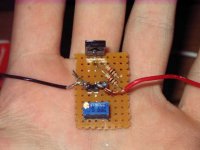
Ouch Johan that makes my eyes bleed....
Very scared of those exposed bits of wire, and would recommend a solid core wire rather than stranded with those veroboards...
Make sure to leave only enough exposed wire to make it through the hole..., the heat normally makes it shrink back even more...
Even better buy some heatshrink and push it up the wire first do your soldering and slide it down against the board to insulate the exposed bits..
Did you look at the bias servo boards on Greg's site a little...?
I see you went with a layout I have not seen before for this piece... which brings with it, its own risks.... try to build onein the standard form... I find a veroboard strip of 7 by 3 holes is perfect...
While you have the board off, desolder the bd139...Now you will learn, next time to solder that transistor flat, as opposed to in the holes... (they just make it hard to remove afterwards)
Test the transistor with your multimeter on diode check mode...
from one pin on a transistor (base), there should be one way connectivity to the two other pins.. will show a forward voltage drop in the range of 500 to 700mV on the screen.... it must not conduct when you invert the probes or be able to cunduct between the other pins...
You don't even need to know which pin is which to test... start with the negative probe on a leg, and test to the other two... if nothing, invert probes, and do again.. if nothing move to the next pin until you find the pin that conducts to the others, then make sure it does not conduct when probes inverted...
http://users.tpg.com.au/users/gerskine/dxamp/dx amplifier-04.htm
now rebuild that little board into something that will not be a permanent hazzard
this is called a diode test...
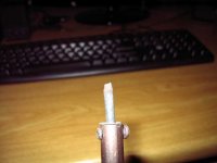
Hmmm.. long day. Some bad news; my soldering, she is broken! Completely; seems at some point today it got knocked off my desk, took the entire tip off on the way down. Put a photo up.. Its alright I guess, wanted to get a new one, that thing wwas old and rusty
But now I have to wait to get paid before I can buy one and get soldering again, or cart all my stuff into varsity and try solder there. So, I thought I'd push on with that diode test... my iron acts as a pretty good area of effect solder nuker now, so getting transistors out shouldn't be too difficult =)
Sorry about my messy bias.. Never been the neatest designer :/ A couple questions; I have used 2 1k resistors to make up the 2k resistor; this should be fine, not too much leakage? Guess I could go buy some 2k's... Just lazy, and petrol to mantech costs so much, especially from tomo on. I can probably build those boards at uni, so small, and I can run one of their nice soldering irons with some extra solder along all my bigger board's tracks, sounds like a plan.
Lastly, I'm gonna get the 2sc5200's out my burnt amp, and scrape it away, but im pretty sure its a fake... My best bet for getting the real thing is Communica I guess?
Attachments
Yep, although insist on non-Toshibas, they stock two other copies, but also seem to have been taken by whoever is selling those fake toshiba's
They are about R17 each.
I took a few of those last week, so far they are not behaveing too badly.
Yep, man throw that iron away... it belongs on an oxwagon...
It is like doing waterpainting with a stick to try and work with that. You will thank me later when you get yourself a nice little station.. I know times are tough... but I would insist on a decent soldering station before a good multimeter...
Edit: scratch those toshibas too... just been speaking to carlos, had some issues fine tuneing Vbe's. based on results he says those toshibas are fake too..
Try to get the ISC ones, I think that is the best of the local stuff unless you want to buy a hundred of each from EBV, the local toshiba distributor....
I will try to bring in a few of the original transistors next month through digikey... At about $2 they are still cheaper than buying the rails localy...
Hmmm... I've had no luck finding any other SC5200's, I'm thinking I'll have to phone communica, go through them.
I broke mine open... Quite the mission, messed my hand up a little doing it; only got the big pliers out half way through and did it properly... You can see from the scuffs. I've included the picture of mine... It doesnt look like that fake you put up nordic, im not too sure if it is, let me know what you think. A question though, not too sure how technical it is, and just out of personal interest; Why aren't the other two legs soldered on? I've studied JFETs, BJTs and MOSs theoretically, but never physically; Why are these transistors built like this?
I broke mine open... Quite the mission, messed my hand up a little doing it; only got the big pliers out half way through and did it properly... You can see from the scuffs. I've included the picture of mine... It doesnt look like that fake you put up nordic, im not too sure if it is, let me know what you think. A question though, not too sure how technical it is, and just out of personal interest; Why aren't the other two legs soldered on? I've studied JFETs, BJTs and MOSs theoretically, but never physically; Why are these transistors built like this?
Attachments
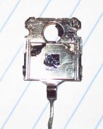
Yep, those don't look too bad...
much better than the one I got.
the die is mounted on the rear plate for heat dissipation... the tab at the back is, as you can see, directly connected to the centre pin, this gives a solid subtrate to handle i nthe machine as well as allowing for heat dissipation through the PCB traces.., the other legs are just connected with silkthread thin wiskers of wire to the die.. kind of puts the wire thicknesses we use to shame... if the other legs were soldered on, it would be a dead short with the centre pin
If you have removed and checked each transisor and still not made progress, feel free to overnight it to me to check it out for you...
Long couple of days, sorry for no updates.
Thanks for the offer Nordic, but I really want to try do it by myself first.. If it's totally hopeless, I'll swing it your way, but for now It's my project.
I have really tough week up ahead, work wise, so I won't be able to get much done. I should be getting a soldering iron during the week, a R500 effort, it looks quite nice. A couple of questions on soldering though; I've always considered myself quite good with an iron, but maybe I'm not. Variable temp control is only really required for IC's, not so much transistors, hey? I attempted to apply heat at even intervals; I'm not sure how much damage irons are capable of doing to some of these components. And could someone send me a photo of good-looking solder on a board; I would send in mine for judgment, but my digital camera just died on me. Finally, the solder itself; nothing special required there. I have.. solder.. don't know where I got it, had it for quite a while and I've almost run out so I'll need some more, but for the most part, electrical solder is electrical solder, am I right?
Nordic, so these transistors look good? Think I should be buying another one to replace the one I broke, or waiting for something other than toshiba's to come in locally. I've got the 2sc5200 datasheet on me... cant figure out a worthwhile diode test for it though, to check out my other one. and there's no possibility the 2sc1943's are fake?
I have mid semester break in two weeks, im off to a music festival for the first couple of days, but following that I will have lots of time to work on this project. Until then, I'm going to just learn as much as I can about building amp's, I've booked Doug Self's book at my uni library, so I'm going to educate myself for now.
Thanks all, later
I think you should increase the size of the 2k2 resistor to the next size up next time, and see if you can adjust bias over a larger range...
As explained before the negative rail draws less current than the positive side... so you just need to measure the + rail during bias.. for now.
I would continue useig those transistors.
I think you will enjoy your nice soldering station... it realy moves things up a few notches...
I think it is nice to have an adjustable temp... too cold, and you have to linger on a component before the solder flows, too high, and the flux has evaporated before you start, and the solder turns to balls of useless snot.
I use about 350C and try to keep a count in my head of about 5 seconds max to apply solder... then waiting a few seconds (maybe solder a leg on another component). Generaly though 60% of sodler spots probably takes less than a second..
Remember to get some diffirent sized points, a nice fine pencil point, and a smallish flat screwdriver tip shape..
- Status
- This old topic is closed. If you want to reopen this topic, contact a moderator using the "Report Post" button.
- Home
- Amplifiers
- Solid State
- My first amp