Hi all,
i wonder if anyone out there has any info on this manufacturer and this power amp in particular?
The manufacturer is Audio Concepts and according to the label on the unit they were based in Kings Lynne, Norfolk, U.K.
The amp in question is the Legend P300 power amp, dating as far as i can tell from the early 80's (a sticker from "Securicor" is dated 11/8/83 being the giveaway here!).
I have googled unsuccesfully, there is absolutely nothing out there at all. There seems to be an American company now using the Audio Concepts brand name though.
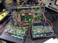
One channel output stage has failed, taking out two of the 6 MosFets. Removing the faulty transistors improves things considerably, now only -6volts at the output (still no signal) instead of the full -ve supply rail.
Does anyone remember this amp and does anyone have any info, especially the schematic?
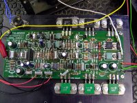
A couple of pics are attached.
Hopefully, Percy.
i wonder if anyone out there has any info on this manufacturer and this power amp in particular?
The manufacturer is Audio Concepts and according to the label on the unit they were based in Kings Lynne, Norfolk, U.K.
The amp in question is the Legend P300 power amp, dating as far as i can tell from the early 80's (a sticker from "Securicor" is dated 11/8/83 being the giveaway here!).
I have googled unsuccesfully, there is absolutely nothing out there at all. There seems to be an American company now using the Audio Concepts brand name though.
One channel output stage has failed, taking out two of the 6 MosFets. Removing the faulty transistors improves things considerably, now only -6volts at the output (still no signal) instead of the full -ve supply rail.
Does anyone remember this amp and does anyone have any info, especially the schematic?
A couple of pics are attached.
Hopefully, Percy.
Attachments
hi Percy,
i have no specific information on your amp but i can tell you that a suitable replacement for the output mosfets which are now obsolete
Renasas 2SK1058 and 2SJ162 (nice and easy to get in uk)
things to note in replacing with above
the package is compleatly different, but im sure looking at your pics that you could easily mount the new parts which are single hole fixing, dont forget insulators.
the pins on the new package is different to the originals, try to use at least one original hole on pcb, this will mean the part may have to be mounted to one side, keep any wiring short.
replace all the output transistors on one channel, not a good idea to mix them and this way you will have a few spares.
when first powering up check IQ also output for any sign of rf oscillation dont know if you are familar with this proceedure?
good luck
burbeck said:
the pins on the new package is different to the originals, try to use at least one original hole on pcb, this will mean the part may have to be mounted to one side, keep any wiring short.
Are you sure about the different pinouts? I just looked at the data sheets and unless im reading them wrong, they're identical:
http://www.tranzistoare.ro/datasheets2/46/46464_2.pdf - 2SK227
http://www.ortodoxism.ro/datasheets/HitachiSemiconductor/mXyzruwz.pdf - 2SK1058
Replace all the outputs, and I'd say to match, replace them in the working channel too. Check the driver transistors - at my guess that's the TO-220 devices shown on the right of the picture.
A list of all of the transistors might be an idea!
hi
well no im not sure, my memory fades getting old. but then it might be a good idea for the op to check this point out, yes that means looking for and comparing data sheets.
dont touch the original working channel until you fix the bad one, use it as a reference.
and yes get a list of the other semis on the board and test them
Legend P300
Thanks for all the replies folks,
I have dry measured all the semiconductor devices in the faulty channel and all measure good. However when powered i am getting about -6volts at the output so there's a faulty passive component somewhere or one of the semiconductor devices only fails with current through it.
A circuit is what i really need! I have started to try and draw the circuit out, very slow indeed, but i'll percevere (not sure if THAT's spelt right!!).
The output MosFets are Hitachi branded and i've been told the circuit may be Haitachi based so if anyone has access to any Hitachi circuit diagrams of output stages i'd be gratefull for an e-mail copy.
I've also been told that there was a Hitachi data book produced with info on the transistors they used and possibly some circuits. If anyone has one of these i'd appreciate a copy.
Thanks again all who have replied,
Percy.
Hi all,
i wonder if anyone out there has any info on this manufacturer and this power amp in particular?
The manufacturer is Audio Concepts and according to the label on the unit they were based in Kings Lynne, Norfolk, U.K.
The amp in question is the Legend P300 power amp, dating as far as i can tell from the early 80's (a sticker from "Securicor" is dated 11/8/83 being the giveaway here!).
I have googled unsuccesfully, there is absolutely nothing out there at all. There seems to be an American company now using the Audio Concepts brand name though.
One channel output stage has failed, taking out two of the 6 MosFets. Removing the faulty transistors improves things considerably, now only -6volts at the output (still no signal) instead of the full -ve supply rail.
Does anyone remember this amp and does anyone have any info, especially the schematic?
A couple of pics are attached.
Hopefully, Percy.
Hi
I've just stumbled on this post and I may be able to help you, the amplifier was designed by Barry Porter I also have a hand draw copy of the schematic that he gave me.
Hi msdin
I have just bought a Legend 300W / channel + pre-amp from e-bay (it was advertised as spare or repair) and having opened it up I found quite a lot of damage (carbonised!!) to the 3R3 resistors in the 0V return from the speakers on the pcb that sits underneath (in the main chassis and now I'm really going to have to check both amps very thoroughly (- oh dear). The Power Amps look unaffected - weirdly as the tracks that take the output to the speakers appear thinner than the ones that got fried on the other pcb?? Could you possibly offer any assistance..? I could really do with any schematic / circuit info you have so i don't have to trace out the pcbs
many thanks in advance - all the best
Mike
P300 concepts amp
Hi my dad was the founder of audio concepts ltd in the 80s I have some spares all I still use the amp and pre amp and do have some genuin pamphlets it is am very powerful set up if I can help any one please email me and found a amp on ebay and hope to buy it for a spare as only 2 left in the family.
Thank u all lance bowyer- Lowe son of audio concepts
Hi msdin
I have just bought a Legend 300W / channel + pre-amp from e-bay (it was advertised as spare or repair) and having opened it up I found quite a lot of damage (carbonised!!) to the 3R3 resistors in the 0V return from the speakers on the pcb that sits underneath (in the main chassis and now I'm really going to have to check both amps very thoroughly (- oh dear). The Power Amps look unaffected - weirdly as the tracks that take the output to the speakers appear thinner than the ones that got fried on the other pcb?? Could you possibly offer any assistance..? I could really do with any schematic / circuit info you have so i don't have to trace out the pcbs
many thanks in advance - all the best
Mike
Hi this is lance bowyer Lowe my dad started audio concepts I have parts for the amps and pre amps I might be able to help . 07880745518 . I still use the amp and pre amp .
@Power amp 300
Please read the rules regarding offering parts and service. This thread is now closed.
You have a new thread here:
https://www.diyaudio.com/forums/swap-meet/377593-audio-concepts-p300.html#post6800188
Please restrict all posts related to sales for this item to this new thread.
Please read the rules regarding offering parts and service. This thread is now closed.
You have a new thread here:
https://www.diyaudio.com/forums/swap-meet/377593-audio-concepts-p300.html#post6800188
Please restrict all posts related to sales for this item to this new thread.
- Status
- Not open for further replies.
- Home
- Amplifiers
- Solid State
- Audio Concepts. Legend P300.