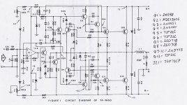
Hi,
I'm new to the group and I was curious about adding extra transistors to the output of this amp. Personally, I think it needs at least 2, possibly 3 more of same but I was also considering putting flat packs instead of TO-3's. Would it be feasable to just use the 2SD718's. I know the gain is less by about 15 points.... Would it work? If I used same outputs, how much would the bias current go up to equal what I currently have (75mA) which is measured in either of the rails. I pop the fuse and replace it with an ammeter, set the bias at 75mA and go on.... I have built 7 of these amps for home theater. I used 2 for 2 subs but they don't like 4 Ohm drivers as they are, so I use them for a small PA system and have a Crown CE-1000 powering my subs. The TA-3600's are specd as 300W into 8 Ohms. NOT even close.... they measured 244W right before clipping, at my work. The output voltage drops too far and the heat sink gets very warm as it is too small. Into a resistive load, they put out 368W into 4 Ohms! I built them from complete kits less pwr. supply caps and bridge rectifiers. I suppose they were so cheap in price as I believe Mark 5 to be out of business now. I'm really happy with them so far but want to be able to change the design to make it more robust. Can anyone with experience in Quasi Complimentery amps help me out here? It sure would be appreciated!
Thanks in advance,
Chris
PS, I'll post the schematic in the next post.... I have to make it smaller.....
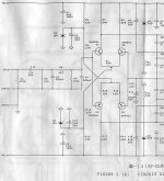
I built one of the Mark V kits. The AF-3 amp, 300 Watt MOSFET amp based on the 2SJ162/2SK1058 lateral mosfet output transistors.
One thing I noticed is that the heat sinks are small compared to other amps of similar rated power. The manual states that for long term high power conditions to use a cooling fan. Otherwise you could try lowering the bias current but if you are pushing the amp hard already that will not help much at all.
Since you have built many of these kits I hope that my next question does not offend you. Are the power supply rails sagging at peak power? That would also drop the power. Transformer, rectifier diodes, caps etc....
If you use lower RDS-on MOSFETS you need to watch that the input capacitance is similar to your original devices in order to maintain bandwidth and that the turn on voltage (Vgs on) for each channel device is matched as close as you can.
Sorry if you are looking for more specifics on the devices you mentioned then I have wasted your time.
As far as my amp goes, I used the amp for my center channel speaker for a few movies. Then I borrowed my dad's old W-5M tube amp and was converted to tubes. I spend a long time building that thing too since Mark V ran out of the chassis and I had to get another source. I even had a custom built toroid from Telema with dual secondary outputs so that I could regulate the low current voltage amplification stage. The transormer, starts to hum when the line voltage gets above 120volts, I used a Variac. The transformer should be big enough since it is rated for 1000VA and it cost me $142. I was told that buzzing is normal for toroids.
I never tried it at high power settings since I was using it as a center channel amp. Funny, since I built a big 20 amp power cord with hubbel hospital grade plug for it too.
I could sell you the pcb, transformer or any part of the kit or the whole thing completed. I have all the documentation. The part that it not robust is the chassis. Let me know if you are interested.
Thanks for the reply....
No, I'm not offended and YES my supply voltage drops. Actually, I'm a bit disappointed in that as torroids are supposed to be more efficient. NO, for a torroid to hum isn't supposed to happen last I read, but I'm really not an expert on them..... I appreciate your offer but I'm sick of mosfets as I'm sick of trying to find a source where I can buy them. High power amps need to have matched sets and who will do that for you? Now you are left with buying a bunch and hoping to get one complete set of matched devices?........ Not worth it to me. Bipolars are so much cheaper and many hi-fi designs out there use them...... I would be interested in a copy of the schematic as I'd like to compare it with other mosfet designs that I considered (Anthony Holtons). I realize that the FET's are different but the concept still seems interesting.
Tube amps.... I'm currently fixing a guitar amp with tubes. Jeez, I have no ideas on what commonly goes wrong with them so they are a thorn in my side for now. I haven't physically heard a hi-fi tube amp but the ones I have heard in the shop (pro audio) are extremely noisey and lots of 60Hz. I know that the gain is way too high on them though........
Maybe you could post your AF-3 schematic as I did with mine?
Thanks again, for the reply,
Chris
I think that Krell uses bipolar and not MOSFETs, at least the ones I saw in the 1980's did. Just have to watch heat more closely to prevent thermal runaway.
The AF-3 schematic shows 2SJ50 and 2SK135, but they later changed it to 2SJ162 and 2SK1058 MOSFETS that are the highly regarded ones, that is what they sent me. The two Xs on the supply rails are where I isolated the diff amp and darlington section from the output section in order to provide more regulation for the voltage amplification in order to improve the noise level even more.
I think that my transformer core may be saturating because they did not design it with enough headroom to handle our line voltage of 122 to 125 volts.
In fact my Dynaco tube amps have transformers that buzz mechanically a little bit too because they were also designed for closer to 110 volts not 120 +. Otherwise the amps are very quite great sounding tube amps.
I have two Dynaco Mark III monoblocks for my left and right channels. They replaced my McCormack DNA-1 two years ago. Center channel and right rear are powered by my Dynaco ST-70 stereo tube amp. The back left is transistor powered with my Hafler P3000. Once I fix up my dads W-5M, it will power the center channel. My powered sub has a 200 Watt transistor amp.
The W-5m is noisy from old electrolytic caps and some corrosion. The ST-70 has the modification from AVA and uses an inferior tube that makes occational clicking noises. The Mark III have the Triode electronics modification PCB from NED at Triode and sound great.
Only drawbacks are as follows, not very powerfull for rock concert level, lots of heat, fragile, expensive tubes to replace, high voltages, and take a minute to warm up.
I use them anyway because I like the way they sound. Very clear and musical. Things sound more real with em....
Hey thanks for the schematic,
Please tell me more about your seperation mod.....
I just got a couple of Peavey transformers from their PV-8.5 amps. They deliver 850WRMS into 4 ohms bridged so the transformers should power a 600-800W amp!!! I think the rails will be +/- 90V when rectified and filtered.... WOW!
What are the tube numbers that you use and from what companies.
We use Sovtek and Svetlana tubes mostly, in the pro audio scene. Many Fender and Peavey amps. We have real good luck with them..... People ask for "Groove Tubes" but where they made? Sovtek and Svetlana........ I prefer Russian tubes over those POS Chinese tubes. Isn't there anything that comes from China that isn't CRAP? Sheesh..........
Thanks again,
Chris
The PCB was really easy to separate the V+ and V- signals as shown by the two hand drawn Xs on the schematic, one was a jumper anyway and the other was an easy cut trace.
I went all out with my power supply, or so I thought. The transformer had four, secondary pairs with 55volts AC at 10amps (before regulation) for the MOSFETs power and 70 or 90 VAC at 1 amp (can't remember right now have to find the transformer print to be sure) that gets regulated to + and - 60 Vdc via a zener/transistor regulator for the diff amp and the dual darlington pairs. I also used HEXFRED diodes for the four bridge rectifiers (16 HEXFREDS!). The idea being that instead of having one bridge in a center tap as ground type config to make + and -, instead, you use dual secondaries and one bridge for plus and one for minus and tie the negative out of one bridge to the possitive of the other to get ground. This is to provide more isolation from any possible 60/120 Hz getting into the power supply.
As far as your 90 volt rails, the MOSFETs should be fine, mine are rated around 200 or 300 volts, I think. Just be careful in the diff amp and darlington section because they usually have a bias current based on a given, expected range for the voltage rails. Maybe you could regulate that section down like I did. Sounds like that is why you asked in the first place. To bad they don't make a cheap regulator and call it an LM317HV (higher voltage) or how about LM7860 for 60 volts and LM7960 for -60Volts. Oh well, more work. It was nice that my amp also came with the speaker protection relay circuit in case I messed it up. If all is well the relay clicks and connects the output to the speakers a few seconds after power up. If the output signal is not ok then it opens up; like when one of the FETs shorts to V+ and tries to send 60 volts to the speaker.....I tried it on a cheap speaker first anyway.
The Heathkit W-5M and the Dynaco ST70 and Mark III are still in demand partly because they used very high quality output transformers. Although some versions are better then others depending on when it was built etc.
Tubes:
The Heathkit uses KT-66, I have my dads Mullards and the Chinese versions. Supposedly they did ok with the KT-66, we shall see when I get it fixed up. Nobody else makes a KT-66 for an ok price.
The Mark IIIs have two Svetlana KT-88 tubes per amp and the ST70 has four Svetlana EL34 (two per channel). I would like to have Mullards from back in the day (NOS) from what everyone says about them but I don't have money burning holes in my pockets either. So the Russians will do fine, I have also heard good things about the Electroharmonix tubes, the upper line of Sovtek. Some of the Tesla or JJ, don't remember the story about them right now but I think they are made in the Czech republic, are supposed to be good too. From what I understand of Groove Tubes: they don't make tubes, they just buy them, test them/screen them according to what they think is good and then label them and match them with the data. Many other companies do that as part of their service to sell you the tubes. Triode Electronics and Upscale Audio have been very good to me the few times I used them and Upscale is supposed to have a very cool setup.
The AVA mod in my ST70 uses 6GH8 tubes instead of the hard to get 7199 (??). However, the 6GH8 were apparently not intended for audio and make the occational pop/click sound. Some day I will fix that as well. The AVA mod is not rated very well anyway and I would like to try the pcb mod that Ned sells at Triode. I don't remember what the other smaller tubes inside the amps are but some are vintage quality.
Apparently there are lots of discussions about the quality of the caps in the signal path. Some people like the lushness of the Jensen paper in oil caps and others swear by the accuracy of the Infini cap on and on it goes. Same with wires (I like pure Silver when I can afford it), resistors etc....
HV regulator
They do make it.
It's the TL783. It goes from 1.25v to 125v, though limited to 700mA. It should be more than enough for low current stages.
The only catch is that you need 2 pairs of secondaries, completely separated, because you will have to do two positive regulators and join them later for the ground.
Pity I couldn't get any people that used it on this Forum to see how it works.
Carlos
audio_schef said:To bad they don't make a cheap regulator and call it an LM317HV (higher voltage) or how about LM7860 for 60 volts and LM7960 for -60Volts.
They do make it.
It's the TL783. It goes from 1.25v to 125v, though limited to 700mA. It should be more than enough for low current stages.
The only catch is that you need 2 pairs of secondaries, completely separated, because you will have to do two positive regulators and join them later for the ground.
Pity I couldn't get any people that used it on this Forum to see how it works.
Carlos
SY, I have a cloned version of the TA800 MkII, built 6 yrs ago. Works, but overheated about 4 yrs ago. Revived it recently and discovered that the bias current (for both channels) will suddenly rise to 1.5A (from around 20-30mA) if I crank up the volume. It will stick at 1.5A until turned off and turned on again. This is the cause of the overheating.
Mine was built from a complete kit, except that I have changed the dual op-amps to LM833, with MJ15003/4 output. Using TL072 op-amps still cause the same overbias "sticking". Using back the NE4558 op-amps that came with the kit solved this problem...... Oscillation? When the bias current sticks at 1.5A, the outputs remain normal ie no high DC voltages etc. In fact, the amp still works normally with the bias stuck at 1.5A, even the built-in speaker protection circuit did not trip.
DC offset for this kit is a high, at around 150mV. Any thoughts? Thanks.
I have this amp, I purchased it used from a buddy 20years ago, it still works and is my center channel. He spent about 600CND to build it using very large capacitors and transformer. Anyway mine is barely putting out any heat. My question here is how am I supposed to adjust the gain/volume pot? Is there any risk in turning it up completely? I find that the higher I turn it the more dynamic the range is. So naturally for movies, I'd like to turn it up as high as possible. Any advice?
- Status
- This old topic is closed. If you want to reopen this topic, contact a moderator using the "Report Post" button.
- Home
- Amplifiers
- Solid State
- TA-3600 amp