Hi all.
What is the purpose of the led in the Vbe Sony. Why?
Geirin
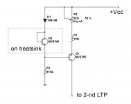
I have a Sony amp with this kind of Vbe multiplier circuit. It hase some issues, sometimes it is working fine, other times the bias voltage is zero (0) and amp goes in protection mode.
Reading this thread got me thinking that it might be oscillation in the Vbe circuit? The reason for this, is that by connecting my multimeter across B-E on NPN transistor, circuit works stable....
Could this be oscillation? And what would be the best way to control it?
")
Edit: See picture in post #10
Well, find your multimeter capacitance and put it across the B-E junction. You seem to have proven that that works already. However I think this method may create RF peaks elsewhere. In that case I would take a stab at a 4.7nF cap across the B-E of the slave. If that didn't work I'd simulate the whole section, but that's just me.
Hi Guys
Kean, I believe D.Self would disagree with you regarding the importance of the bias generator inasmuch as he asserts that Vq is the "all important" output stage quiescent factor. The generator just has to cancel Vbe changes of the output stage with temp, and maintain Vq. (pg.184 APAD5).
It is funny that Self also moans about the CFP gen being "too complex for such an important circuit" and then presents his floating bias opamp for the class-A amp. That struck me as quite a contradiction. However, it makes me wonder why direct bias control is not used more, other than because of its cost. It would certainly allow precise control over Vq and other tempco issues disappear. I use direct control in my class-A amps.
Maybe I'm just lucky with my builds, but the CFP gen has never been a problem. I use a 10uF across it.
Some will note that often two multipliers are used. This allows ambient and BJT tracking in independent circuits. It also allows the use of a PNP in one and an NPN in the other if ones needs that kind of tracking.
Have fun
Kevin O'Connor
Hi All
I do not now of the thread is still active but have a question about a temperature correction for a circlotron.
I have put it on a spot between the reference resistors, I did try with a schematic I had get from a friend here who was so kind to draw it for me.
I need a regulation who do not make impedance smaller but higher, so resistance needs to rise instead of drop what normal vbe does.
someone an idea to get it better, this one do work quite fine but has a little overcompensation, what can I do to make thet smaller, a resistor in the sense transistor? a mosfet did not work wel, it has to low compensation, possible because I did include the drivers also in this idea.
I can use the Sziklai complementary pair as an idea because of the very low impedance however I need a regulator who do let impedance get up to lower the idle current, I have to invert it before use, and I need to adjust the servo so it does not overcompensate.
some tests here. YouTube
You see some difference in current but this is because of resistors not so precise in the test build, not of importance further.
thans in advance.
kees
Attachments

Last edited:
The Vbe multiplier needs to track well the output transistors temperature.
Over adjusting will cause crossover distortion and too little adjusting can start to cook output transistors.
Another view is the bias current. Some people like lots of bias current to get a better sound. On the other hand the likes of Peavey like minimal bias current to keep output transistor temperature down. I am with Peavey on that and tend to use minimal bias currents on my designs either bipolar or mosfet.
On my own amps I tend to overcool the amp so over heating is not a problem.
Big heat sinks and cooling fans are my way around it.
I had a mobile disco where the fan failed. I had my pint on top of the amp and couldn't work out why my pint was warm !
I touched the case and it was hot. Luckily the amp survived till the end of the gig.
I replaced the fan then added another one as failsafe.
Last edited:
Hi Nigelwright.
I have no peavey but it is a home sound system, I do not the old days as discjocky well, I was one, and had a self build amp with the first toshiba laterals in it, and get hot, but it has work for years, and current settings was just 100 ma echt fet.
here we have verticals, and the circlotron has it,s multiplier moved from the preamp vas to the ground reference resistors where it work very good but I have overcompensation, it may some lower, and the point where the multiplier is, is very low impedance, still it works wel, and therefore I did has the question about the szliklai pair who is quit good suited for low impedance points, however, I need a positieve tracking, impedance needs to rize when temp go up, making the driver get into lower current and with them also the power fets, I like the idea, and it do work, now finetuning.
I have the tracking transistor a mje 340 underneath the power fet, I can try to set in between and then it will get less compensation. it's quite save I admit, but need high quality audio, so I need a very good multiplier.
For professional equipment auto tracking is best see pdf.
https://linearaudio.net/sites/linearaudio.net/files/v9 jd.pdf
One thing people can also be mistaken in that is the heatsink itselfs, it do need to be choosen wisely to get the best tracking.
regards
regards
Last edited:
The Vbe multiplier not only needs to track the OP transistor temperature but also provide exact compensation. The CFP seems to work best with MJL3281A OP transistors. The circuit was first mentioned in this forum in "class B high feedback" thread from 2006, posts around 350 on.
I expanded on the principle in post #6 in response to Carlos's"Help me to improve our prehistoric Vbe multiplier biasing system" thread in 2015.
It is not a perfect system even then: the junction temperatures of the transistors will run hotter than the heatsink, so a degree of overcompensation may be required depending on the thermal resistances.
These can be calculated, of course, but at the end of the day I have found the circuit of post #6 mentioned to give a stable current with all transistors (drivers+OP+bias) all on the same H/S with either (discrete) pairs or triplets (which need a factor of 6x Vbe).
The Vbe multiplier not only needs to track the OP transistor temperature but also provide exact compensation. The CFP seems to work best with MJL3281A OP transistors. The circuit was first mentioned in this forum in "class B high feedback" thread from 2006, posts around 350 on.
I expanded on the principle in post #6 in response to Carlos's"Help me to improve our prehistoric Vbe multiplier biasing system" thread in 2015.
It is not a perfect system even then: the junction temperatures of the transistors will run hotter than the heatsink, so a degree of overcompensation may be required depending on the thermal resistances.
These can be calculated, of course, but at the end of the day I have found the circuit of post #6 mentioned to give a stable current with all transistors (drivers+OP+bias) all on the same H/S with either (discrete) pairs or triplets (which need a factor of 6x Vbe).
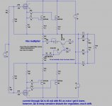
It can be calculated but even then there is no sureness it will work fine, I have in schematic also a vbe who has 40 mA through it because of the place it is in to and it needed inverted because I need a positive action, I did now change the current through the sensing resistor, and now it go after a whil go into runout, so that is not very good, with 2,2 mA through the mje 340 transistor, but can I use the CFP (because of its low impedance) to track positively or negatively? also, the heatsink itself is a uge factor who is difficult to calculate, and I am not a math boy.
regards
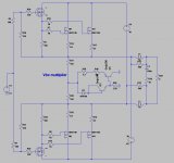
Here some test sim with CFP do not work, it helps the runout because it is on this amp the other way around, I need higher inside resistance from the Vbe, this do not, trying both npn pnp and vica versa did also not work.
A extra transistor on the base of first transistor maybe? ideas how to get a low impedance multiplier.
And the version I have do jump up and down some 20 mA if it is settled, so looks unstable.
Last picture I have use a temp sensor and the CFP, but seems to get uge compensation, to much but not tested in real live.
regards.
Attachments
Last edited:
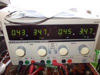
After putting the sense transistor on the top of the irfp240 I get quite stable respons, even until the heatsink is very hot using a cloth on top, (almost burn vingers) staying between 390 and 430 mA.
Butt after a longer time, it does go up to 520 mA, but that needs longer time, so it is now a little undercompensated I gess, need th change the current through the sense transistor.
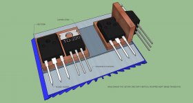
Quite difficult stuff, but I have a solution I thing what will work, making a copper piece put sense transistor on it and the copper piece between the irfp240 and the isolator and then on the heatsink will give a tight temp sense, copper do fine here.
Now again 10 minutes later, it stays around 510 mA, and the heatsink is not that warm, the verticals also need a higher idle current because she like it hot. I put it to 250 mA each, that will work fine.
regards
regards
Butt after a longer time, it does go up to 520 mA, but that needs longer time, so it is now a little undercompensated I gess, need th change the current through the sense transistor.
Quite difficult stuff, but I have a solution I thing what will work, making a copper piece put sense transistor on it and the copper piece between the irfp240 and the isolator and then on the heatsink will give a tight temp sense, copper do fine here.
Now again 10 minutes later, it stays around 510 mA, and the heatsink is not that warm, the verticals also need a higher idle current because she like it hot. I put it to 250 mA each, that will work fine.
regards
regards
Attachments
I have not designed a bias stabiliser for FETs, but I suspect it should be built with a FET similar to the OP transistors at least to maintain some degree of matching. FETs exhibit negative TC below a certain current then switch to PTC, except the current changeover point tends to be too high to utilise as a quiescent current, unless the amp is operating in a mostly-class-A mode. Therefore I suspect it would need careful selection of the FETs to match the Vg's at the quiescent current in the OP devices and operating (VAS) current in the bias stabiliser.
However, the CFP can be arranged to give a range of TC's so it may be possible, by measuring the performance of the FETs you are using, to match theTC's of the output using a combination of CFP and resistors.
However, the CFP can be arranged to give a range of TC's so it may be possible, by measuring the performance of the FETs you are using, to match theTC's of the output using a combination of CFP and resistors.
I have not designed a bias stabiliser for FETs, but I suspect it should be built with a FET similar to the OP transistors at least to maintain some degree of matching. FETs exhibit negative TC below a certain current then switch to PTC, except the current changeover point tends to be too high to utilise as a quiescent current, unless the amp is operating in a mostly-class-A mode. Therefore I suspect it would need careful selection of the FETs to match the Vg's at the quiescent current in the OP devices and operating (VAS) current in the bias stabiliser.
However, the CFP can be arranged to give a range of TC's so it may be possible, by measuring the performance of the FETs you are using, to match theTC's of the output using a combination of CFP and resistors.
Hi John
mine problem is I need a inverted action of the vbe multiplier, when most need negative I need positive, so resistance needs to go up here in stead of going down like between the basis of the driver transistors, I have a diferend amp, a circlotron.
as I now see, after adjust the sense transistor idle current, with 1.2 Kohm it does track quite good, when I do let it heat very much, then it overcompensates a little dropping it 150 mA, but only when it is so hot I can not toch it.
I do not now if i can use a mosfet, I have now a mje 340 diode connected, and a buffer inverter mje 350 who however is als temp sensitive but just in the other direction, so these do when both on cancel the regulation therefore the buffer has a heatsink, it draw 40 mA there because it is in the ground reference resistors.. AC do cancel out there and is not a problem.
have some drawn for how to get a good tracking, using on top do work but after it gets to hot runaway do occur. @eva is right here, it does work, but is dangerous for professional stuff.
regards
Attachments
Here some test sim with CFP do not work, ...
regards.
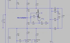
Here is something I would try. Use a FET to give you FET thermal behavior. Note that this is a current regulator, which becomes a voltage going through the gate resistors.
Attachments
Here is something I would try. Use a FET to give you FET thermal behavior. Note that this is a current regulator, which becomes a voltage going through the gate resistors.
Hi Steve
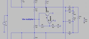
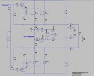
I have a circlotron who I have setup that the current regulator needs to get a higher resistance when warming up, for this I have use this schematic, but because there is more current present, the buffer inverter transistor has 45 mA through it and get warm and as such give also a disturbance because I need a buffer inverter who is not sensitive for drift when get warm a CFP has not I did hear?, but can this can be used with a temperature sensor as in schematic?, cooling the buffer with a quite big heatsink do stop the extensive drift, now I get as I do start up the test amp is stabilizes around 500 mA stays there for more then 30 minutes then drops suddenly to 330mA the go up to 620 mA and drops again to 510 mA stays again and repeat again.
Because I have the multipier into the ref resistors I get higher current of 45 mA through the Q4 buffer inverter, the audio signals get canceled there so these are not relevant.
I need to have a buffer inverter who do not drift, the sense transistor maybe can be a mosfet, gate source voltage a issue, a normally VBE multipier do get lower resistance when get hot, and
as such do regulate the idle current, however I need a higher resistance because I have not such a system but it is from ref resistors to ground, lower resistance menas here higher current, a normal multipier is here not usable, so a buffer inverter is needed who do not drift, this is very important.
Just play some with asc included.
thanks for respons.
regards
regards
Attachments
Last edited:
Wel I have now use a CFP , it does invert also and I think when I put Q1 and Q 2 together so it has thermical connection I get rid of the drift.
Now we need to replace the sense transistor for a fet, but do not now ith that is possible because of gate source voltages, using voltage from the LPT supply
is possible to get it working through a resistance devider, or maybe more easy adjust the temco of the transistor because this do work also. Putting a mosfet as diode is maybe less accurate.
And thanks all for the tips, making a good multiplier who do regulate precise is quite difficult.
regards
Attachments
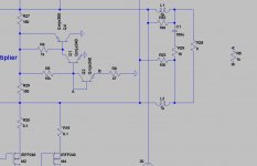
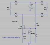
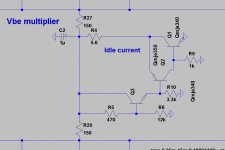
I have play some more, the circuit is in the pic, it keeps quite stable but I do now now for shure how to adjust the temco, I can do it by current to temp transistor however these do have variation when adjusting.
as I did in schematic it is stable within 50 ma and after passing the 70 degree it drops 100 ma after some 5 minutes it do go back to adjustment point.
Sometimes I see a suddenly drop, but this was with all cases so maybe bad chinees mosfets? or damaged ones.
Do watch out because mine multiplier do work inverted, as I do need higer voltage for less current where in normal amps it is lowering voltage for less current and I have more current through the multiplier, 60 ma.
But I have now a different version as first, these is more stable as I did test.
regards
Attachments
- Home
- Amplifiers
- Solid State
- Differences between various vbe multipliers