hmm ok.. hav'nt tried that but it was on my mind.. I will try it..
hmm been listening for a while now, I think the vas cascodes must be put in there again.. (you know what i mean, transistor in series with the vas and base to zener , or 28v or something, think it's called cascodes?)..
Dont get me wrong, I like the sound but...
hmm been listening for a while now, I think the vas cascodes must be put in there again.. (you know what i mean, transistor in series with the vas and base to zener , or 28v or something, think it's called cascodes?)..
Dont get me wrong, I like the sound but...
how hard do I have to drive differential amp to drive the mosfet in 20khz, hmm hmm and funky behaviur when clipping. and I suspect higher 4rd-up harmonics.. hmm nje mosfet did'nt really do it for me.. I think I'll stick to mje340 and maybe 15ohm emitter resistor there.
cascodes doesnt really seem worth it , hmm so CCS is next to try.
Originally I had emitter capacitors in parallell with 15ohm emitter reisistor om mje* but that didnt sound good I cut them out(not from eagle yet though)..
vas is getting quite small signal anyhow so i think bjt will be ok there..
in diffamp I prefer fet, didt get as good results earlier when using some bjt's (remember, compoment count ,they might be better with more transistors)..
If you didnt get it . this is me trying the difference in sound between a 100000 times open loop amp and a similar(the one i did earlier) that has maybe 20000times..
So far .. the earlier amp i did might sound better..
something similar to this one..
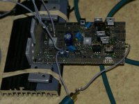
Attachments
Hi,
not much response.
The VAS is working quite hard to drive the output FETs at high frequency, particularly with that tiny RF filter of 22pF.
The Cdom/s of 100pF will limit slew and loads the non-inverting input. What is the capacitance of the bd/MJE VAS?
The uncontrolled currents in the front end will benefit from a low noise, well regulated PSU.
15r for VAS Re is too low. You have about 10mA passing the drain loads. That leaves about 1400mV across Re.
Change the bias pot to be all in the source side of the Vgs multiplier.
What about Zener protection of Vgs of the outputs?
Hi
The circut in post 1 looks like it would work better. The circuit in post 6 has the input/VAS driven by +/- 12V, and cascode for a swing of +/- 6V? Cascoding the VAS does work better, IMO, but it costs a few more volts, not a problem if using a seperate supply voltage as is usually done with a source following output stage. The circuit in post 1 could benifet from the cascode VAS, but I wonder if using a Mosfet cascode, being driven by the BD139/140, would work better?
 Of course you have to take into account Vgs for the cascode DC reference voltage. Since the voltage on the BD139/140 would then be constant at like 5V, you could use a small signal, more linear, faster, higher gain device for the amplifying transistors, and let the cascode devices take the power.
The question I have is why you want to use power devices as input transistors? I think the cascade differentials at the input might benifit better by using small signal J-fet's (or BJT) for the first differentials, and BJT's for the second. The input capacitance of the power Mosfets may be too great for use as small signal input stage. Also I would question the linearity of the power Hex-fets at such a realitively low current as 10mA. Linearity is a very important goal for the first stage(s). Replacing the 2K tail resistors with a CCS is still a good idea. I prefer a self bias J-fet.
I agree with Andrew that 100pf miller compensation is too large and Vgs zener protection. The output transistors may need a gate driver stage. Also the Vgs multiplier is faulty in that the gate is connected to the wiper. If the pot fails and the wiper becomes open, the Vgs multiplier may turn off and the outputs will saturate and release thier magic smoke. There needs to be a voltage divider made with the pot and another series resistor with the gate connected between them.

The circut in post 1 looks like it would work better. The circuit in post 6 has the input/VAS driven by +/- 12V, and cascode for a swing of +/- 6V?
Cascoding the VAS does work better, IMO, but it costs a few more volts, not a problem if using a seperate supply voltage as is usually done with a source following output stage. The circuit in post 1 could benifet from the cascode VAS, but I wonder if using a Mosfet cascode, being driven by the BD139/140, would work better? Of course you have to take into account Vgs for the cascode DC reference voltage. Since the voltage on the BD139/140 would then be constant at like 5V, you could use a small signal, more linear, faster, higher gain device for the amplifying transistors, and let the cascode devices take the power. The question I have is why you want to use power devices as input transistors? I think the cascade differentials at the input might benifit better by using small signal J-fet's (or BJT) for the first differentials, and BJT's for the second. The input capacitance of the power Mosfets may be too great for use as small signal input stage. Also I would question the linearity of the power Hex-fets at such a realitively low current as 10mA. Linearity is a very important goal for the first stage(s). Replacing the 2K tail resistors with a CCS is still a good idea. I prefer a self bias J-fet.
I agree with Andrew that 100pf miller compensation is too large and Vgs zener protection. The output transistors may need a gate driver stage. Also the Vgs multiplier is faulty in that the gate is connected to the wiper. If the pot fails and the wiper becomes open, the Vgs multiplier may turn off and the outputs will saturate and release thier magic smoke. There needs to be a voltage divider made with the pot and another series resistor with the gate connected between them.
Ahh.. many good inputs there.. thanks
And a few that I already knew, like the zeners for gs protection. and voltage diveider for cascode transistor,(dont know why I drew that)
I dont consider irf610 a real "power device" hehe, more like a small signal device trapped in a to220 ;-)
Good about the bias pot, I have to get that fixed!
Hmm Beeing the "irl" person 100pF is from my tests irl, it limits slewrate to about 30V/us or so..
Re I dont get, nothing is said why 15ohm would be too small.
Current through bd243/53(not using bd139 anymore) will be adjusted with other components so that they dont get warm(did'nt really measure it).Is it that higher resistor generally sounds better due to better linearity(and harmonic content therefor)..
hmm now I'm trying Two bd243/53 in parallell with separate higher value Re's, just so see how that sounds.
AHh and about the buffer, I tried that a year ago on another amp and it got way faster from like 20v/us to 60 or somethin like that, but I cant decide now if it's worth it, extra components versus sound.. hmm
Yes I totally agree ccs's is preferred.. but I'm going without for now..maybe I'll try A led and a bd243/53 as a ccs, I did'nt try that..
kifs is somewhat important here :-D less components= better hehe(but keeping the general design idea)
AndrewT said:......15r for VAS Re is too low. You have about 10mA passing the drain loads. That leaves about 1400mV across Re.
I thought I answered that but here goes.nikwal said:.......I dont get, nothing is said why 15ohm would be too small........
The drain load of 200r develops a voltage due to the (balanced) currents passing through the two halves of the LTP.
This drain load voltage appears across the VAS & it's emitter resistor.
As said above, with the set up shown in post1, Vre=1400mV. If Re=15r then VAS current is ~93mA. This is very high and you are likely to overheat the VAS and reduce it's temperature derated SOA (=burnt out VAS).
9mA would be highish and you may find the amp will work with even less.
nikwal said:.....AHh and about the buffer, I tried that a year ago on another amp and it got way faster from like 20v/us to 60 or somethin like that, but I cant decide now if it's worth it, extra components versus sound.. hmm
The way I see it, if you’re going to DIY, why not shoot for something better than you can buy at typical retail? So what if more components are needed, they are generally cheap and you will probably end up spending more money on 'doing it yourself' anyway.
") Best to optimize the topology first, and then choose the proper components you have available. IMO, an amplifier using "linearization" techniques does in fact 'sound' better.
Best to optimize the topology first, and then choose the proper components you have available. IMO, an amplifier using "linearization" techniques does in fact 'sound' better.Maybe buffer isolate vas stage from output transistors making life easier for it and therefore better sound, but about the slewrate as it is now I dont care, as long as it's high enough, could maybe get a bit better by lowering Cdom as suggested, and play around a little with C in feedback..
Now it looks something almost like this.. :-D hmm not sure if I like it or not.. for the moment using Re 18ohm.. going to try the buffer thing, maybe Re will get higher..
Now it looks something almost like this.. :-D hmm not sure if I like it or not.. for the moment using Re 18ohm.. going to try the buffer thing, maybe Re will get higher..
Attachments
Almost feel like I'm spamming but now I've been playing it for a good while with these "Final" changes and I really like it.. It was getting better all the time ,thank you guys(or girls)
ps. And remember, a comment is'nt worth as much witout an explanation(at least a simple one)..
http://hem.bredband.net/nikwal1/zah3.gif if getting updated in the future,schematic will be there..
( if you want ccs insted of 2k, just add it, no sweat)..
ps. And remember, a comment is'nt worth as much witout an explanation(at least a simple one)..
http://hem.bredband.net/nikwal1/zah3.gif if getting updated in the future,schematic will be there..
( if you want ccs insted of 2k, just add it, no sweat)..
Attachments
- Status
- This old topic is closed. If you want to reopen this topic, contact a moderator using the "Report Post" button.
- Home
- Amplifiers
- Solid State
- My amp I'm working on now.. Comments?tips?changes?