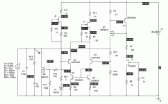
wrenchone said:Attached is a simulated response to the load step shown in the schematic. What I want to know is, how are other high-speed regualtors(Sulzer, Jung) with a similar load step?
This is quite high performance. The change of just 1.5mV at a step response of 20 mA (25mohm) is good, with a step that has 100nS rise- and fall times. A Jung goes down to a few milliohms at 20kHz, IF you do remote sensing (the wire/pcb track to the load will have more than a few mohms).
What would probably be more relevant to audio is the response to a step with say 10uSec rise- and fall times, or the PSRR with a 20kHz load.
Jan Didden
Hi wrenchone,
both nice design and interesting topic! Even more because I'm experimenting on a similar field at the moment. My second task is to compare a diff-amp reg as yours with an open loop 'regulator' both specwise and sonically, for intended lineamp and phonoamp use.
If someone could give some advice how I can perform your step response sim in LTSPice, I could repeat it for my circuits even with the same frame parameters. Is it just to connect a pulsed voltage source to the regulated line and watch Vout?
But first, I have a few questions regarding your design.
1) EDIT: <saw my mistake>
2) How is the voltage reference (R16/V1) made in the real circuit? I've found the actual implementation of the reference will 'top or flop' a regulators performance.
3) Both a cap across the v-ref (better still: R-C- filter) as well as R13 will seriously improve the overall performance, at least regarding noise and output impedance.
Is the impedance between both diff-pair inputs matched? The R of the mentioned R-C filter might provide help, if not.
4) I've seen somewhere elaborated (when memory serves me well on Rod Elliott's pages) that you don't gain advantages by using a CCS in a diff-par tail when using a current mirror. What is your reasoning for still using that CSS?
5) What is the purpose of R2?
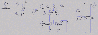
For reference, *not* for dragging the thread OT, here is one of the circuits I'm trying at the moment and we could compare. V2 is a LM329DZ. I have an open loop shunt in the pipeline which I could post as well once I build it in reality.
EDIT: replacing Q1 with a mosfet betters performance about 20kHz throughout the bandwith, at least in sim. I'll try that out as well!
Rüdiger
both nice design and interesting topic! Even more because I'm experimenting on a similar field at the moment. My second task is to compare a diff-amp reg as yours with an open loop 'regulator' both specwise and sonically, for intended lineamp and phonoamp use.
If someone could give some advice how I can perform your step response sim in LTSPice, I could repeat it for my circuits even with the same frame parameters. Is it just to connect a pulsed voltage source to the regulated line and watch Vout?
But first, I have a few questions regarding your design.
1) EDIT: <saw my mistake>
2) How is the voltage reference (R16/V1) made in the real circuit? I've found the actual implementation of the reference will 'top or flop' a regulators performance.
3) Both a cap across the v-ref (better still: R-C- filter) as well as R13 will seriously improve the overall performance, at least regarding noise and output impedance.
Is the impedance between both diff-pair inputs matched? The R of the mentioned R-C filter might provide help, if not.
4) I've seen somewhere elaborated (when memory serves me well on Rod Elliott's pages) that you don't gain advantages by using a CCS in a diff-par tail when using a current mirror. What is your reasoning for still using that CSS?
5) What is the purpose of R2?
For reference, *not* for dragging the thread OT, here is one of the circuits I'm trying at the moment and we could compare. V2 is a LM329DZ. I have an open loop shunt in the pipeline which I could post as well once I build it in reality.
EDIT: replacing Q1 with a mosfet betters performance about 20kHz throughout the bandwith, at least in sim. I'll try that out as well!
Rüdiger
Attachments
Onvinyl -
I have several choices for Vref - a TL431 with resistor network, a reverse biased base-emitter junction as zener, or a stack of 4-5 green GaP LEDs. I'll probably use a big cap across the reference in any case as it slows up the output rate of rise at turn-on to reduce thumps.
The current source on the diff pair tail pins the bias current, even if it isn't strictly needed for comon mode rejection.
R2 reduces power dissipation in the JFET below it.
I may try replacing the bipolar diff pair with a couple of JFETs to allow more latitude in an RC filter for the reference. In that case , I may add sanother stage for more gain (depends on simulation results).
Janneman -
Nice to meet you at Burning amp. I chose the fast current slew rate to fully exercise the high frequency capability of the regulator. The interesting thing about this regulator is that it requires a big, fat cap with low (for an electrolytic) ESR for stability. A lot of fast regulators cannot tolerate much output capacitance without severe bandwidth reduction/oscillation. What you get here may be the best of both worlds - a big capacitor to supply some charge faster than the usual regulator can deliver, and a fast regulator to replenish said charge quickly. More tinkering will tell.
Here is the same regulator with some nice jfets in the diff amp. Tail current was boosted to cater to the fet characteristics. I tried putting a current source loaded emitter follower between the diff stage and the output fet, but that made the simulation really weird and granular, even when the reltol was upped by a factor of 10. I went back to plain vanilla.
Attachments
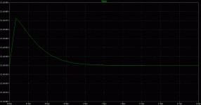
This is the output response with attack and decay times slowed down to 10 usec each. The plot shown is just for the attack. The next thing I might try is to add some gain to the output sink stage with a P-channel mosfet or PNP booster. Some global feedback (compensation) would also be interesting to try.
Attachments
Hi Wrenchone,
I still don't get how you set up your output response simulation. It would really be interesting to compare.
I build a version of my proposal with an additional E-follower and it indeed gave me severe and untamable oscillations.
It might be interesting to compare your results if your v-ref and/or the diff-pair would be referenced to the already regulated voltage line.
Rüdiger
I had to download LT Spice to have a look, but what you do is right click on the current source, use advanced settings, and configure it as a pulsed current source. That's what I'm doing in PSpice, it's just that the pulsed current source is explicitly available in the sources menu without having to dig for it.
I don't think that referencing the current sources to the output will make any difference in the response, but the reference and tail currents will be a little quieter in practice. I'm going to do a some more messing around with sims, but I think soon I'll be ready to spin a prototype.
I don't think that referencing the current sources to the output will make any difference in the response, but the reference and tail currents will be a little quieter in practice. I'm going to do a some more messing around with sims, but I think soon I'll be ready to spin a prototype.
One more note in passing - the current source on the diff pair tail is still needed for line rejection. It's true that the current mirror will tend to force equality in the pair currents, but unfortunately, the signal output from the diff pair is single ended, and any twitch in the tail current will appear at the output.
Hi wrenchone,
thanks a lot for you effort, it is very appreciated!
I will post results later, my results seem to be lower (hundreds of µV), but the resulting waveform looks ugly. In an open loop shunt, the response is both lower and much better looking. I re-check the results, before posting, though.
Didn't anybody set-up an spice-circuit of a jung/didden reg?
here it is explained, that a CCS at the diff-pairs tail does indeed enable CM-rejection, but, if one uses a current mirror, the CSS is not needed anymore. I might got that wrong, of course.
Rüdiger
Hi wrenchone,
originally, I was looking for an explanation, why the simmed performance was the same both for CCS and resistor in the tail. I might have chosen the wrong tests, though.
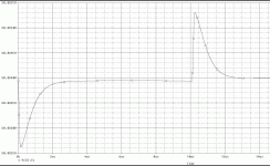
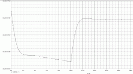
attached is the response for the shown circuit. The pulsed CS (I1) sat at the output of the circuit.
rise and fall time are 100ns, stepsize is 20mA.
It is not very pretty
The effiency of the reg at 10Mhz is -53dB
Rüdiger
originally, I was looking for an explanation, why the simmed performance was the same both for CCS and resistor in the tail. I might have chosen the wrong tests, though.
attached is the response for the shown circuit. The pulsed CS (I1) sat at the output of the circuit.
rise and fall time are 100ns, stepsize is 20mA.
It is not very pretty
The effiency of the reg at 10Mhz is -53dB
Rüdiger
Attachments
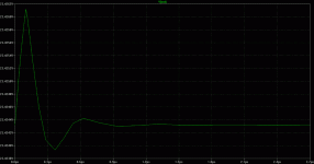
I saw that the response is superimposed by the ESR you allow for the output cap.
My last post was with 0.05 Ohm, with 0.01 things look considerably better. Now, what ESR is reasonable or achievable with paralleling smaller caps?
Rüdiger
EDIT: other screenshot
My last post was with 0.05 Ohm, with 0.01 things look considerably better. Now, what ESR is reasonable or achievable with paralleling smaller caps?
Rüdiger
EDIT: other screenshot
Attachments
- Status
- This old topic is closed. If you want to reopen this topic, contact a moderator using the "Report Post" button.
- Home
- Amplifiers
- Solid State
- Regulator for RIAA Preamp and Line Amp