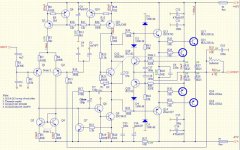
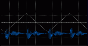
I'm currently in "learning phase" of amp design so I paused work on this amp until it is polished. This is what I have for now (schematic below), it performs nicely in simulations, THD values are very low (also 60Hz : 7kHz, 4:1 below 80dB) except one tiny little thing (?). When the input signal is triangle, I can see some kind of oscillations between + and - input on oscilloscope, so I'm very confused what to do with it and how to fix this issue.
Attachments

Hey Glen ")
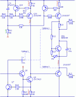
According to the datasheet Q7 will start conducting at 0.6V (t=25C), at t=100C Q7 will start above ~0.4V. Should I lower the R20 to maybe 25ohms, 18ohms is to drastic change?
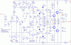
Also I dropped the two pole compensation and used 24pF Cdom to see if anything changes...so here is the picture. I think it's better than previous post, it it?
According to the datasheet Q7 will start conducting at 0.6V (t=25C), at t=100C Q7 will start above ~0.4V. Should I lower the R20 to maybe 25ohms, 18ohms is to drastic change?
Also I dropped the two pole compensation and used 24pF Cdom to see if anything changes...so here is the picture. I think it's better than previous post, it it?
Attachments
blueskynis said:Hey Glen
According to the datasheet Q7 will start conducting at 0.6V (t=25C), at t=100C Q7 will start above ~0.4V. Should I lower the R20 to maybe 25ohms, 18ohms is to drastic change?
Also I dropped the two pole compensation and used 24pF Cdom to see if anything changes...so here is the picture. I think it's better than previous post, it it?
Hmmmmmmm............ I'm guessing that you're looking at a Vbe Vs Ic graph that shows the base emitter voltage at a minimum Ic of 100uA.
100uA is still a significant proportion of your LTP tail current and you really want to avoid collector conduction at currents much lower than this during normal operating conditions (which correspond to an even lower Vbe).
The ambient temperature inside an amplifiers case may rise significantly higher than 25 deg C and you also have to account for variations in the VAS standing current due to temperature drift and component tolerances. Then there is the increased VAS transistor conduction due to the current demands of the driver stage, particularly at 20kHz at full amplitude.
Fortunately though, the operation of the protection transistor can easily be made totally benign simply because there really isn’t any need to limit the peak VAS current very close to the quiescent value. Three or four times the quiescent current generally isn’t a problem, particularly so as the protection transistor operates with a low duty factor. Then you can be sure the protection transistor isn’t going to be conducting when you don’t want it to.
Also, 24pF is waaayyyyyyyyyyy too low for Cdom! Now I've got to run.....
Cheers,
Glen
Then there is the increased VAS transistor conduction due to the current demands of the driver stage, particularly at 20kHz at full amplitude.
Is definitively a reason to change it to lower value, although open loop gain will go up...
Ok, Glen, thanks very much
Nesa
I agree with Glen, R20 is too big on your schematic.
36/39Ohm would be OK, although the best choice would be 24Ohm.
About Cdom I agree too, I would keep the 100pF+510pF values.
Additional rail filtering would be a good idea in the positive rail too. I'd choose higher resistor value and lower capacitor value as parts of the filters.
What does C17/C18 do? Have you checked the driver's and OP's collector current's waveform when protection is active? Doesn't C17/C18 caused overshoots etc.?
Anyway nice design, should sound and measure very good. Reminds me on the Slone/Self designs.
Hi Andy,
I think 24 ohms for R20 is fine. It should start conducting somewhere above 16mA (at temp 100C) which is double than normal.
C17/C18 are part of lowpass filter formed with resistors R39-R42, I saw this being used in PA300 amplifier published by Elektor. Nothing fancy here. Protection isn't active during normal use and it doesn't cause oscillation, overshoot etc.
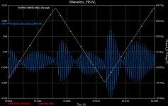
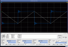
When I use two pole compensation, oscillations are quite different. Maybe it is normal when triangle input wave is applied, is it?
I attached another image.
Nesa
I think 24 ohms for R20 is fine. It should start conducting somewhere above 16mA (at temp 100C) which is double than normal.
C17/C18 are part of lowpass filter formed with resistors R39-R42, I saw this being used in PA300 amplifier published by Elektor. Nothing fancy here. Protection isn't active during normal use and it doesn't cause oscillation, overshoot etc.
When I use two pole compensation, oscillations are quite different. Maybe it is normal when triangle input wave is applied, is it?
I attached another image.
Nesa
Attachments
Additional rail filtering would be a good idea in the positive rail too. I'd choose higher resistor value and lower capacitor value as parts of the filters.
It is very likely I will add RC filter for positive rail to, it looks much nicer
blueskynis said:lowpass
Any motivation for selecting that corner freq. in the V/I-limiter, Riedl picked 1KHz for the PA-300 iirc ?
Hi,
I would set a transient peak current of 14Apk for an 8ohm speaker. Ipk~=Vout/Z/0.35~=40/8/0.35~=14Apk. If 4ohm speakers are used then this becomes 25Apk (150W into 4r0).
Assume the output devices can supply 7Apk each then the driver output is about 400mApk.
At this current the driver gain may be down to around 70 or 80 requiring around 5mApk from the VAS.
That requires 8mA+-5mA just to run the amp into a severe 8ohm speaker. See what I mean about running the VAS hard. And why your protection Q7 will trigger well before peak current is achieved.
The output will source current through the VAS and the triggered protection. If the output is shorted or connected to a low impedance speaker then the EF preceding the VAS is overloaded.
The other thread decided that the best way to protect the EF was to add a collector resistor to limit the current passed from the ground into the EF.
The output base stoppers are a good addition. They may not be needed in which case a 0r0 link can be inserted. The higher this value the worse the distortion becomes. Most settle for a value between 1r0 and 2r2 as a compromise to minimise oscillation and minimise the added distortion. 10r might be OK, but be prepared to experiment with the value.
jacco vermeulen said:
Any motivation for selecting that corner freq. in the V/I-limiter, Riedl picked 1KHz for the PA-300 iirc ?
No, I haven't paid much attention to that. Current values give corner frequency of about 2kHz? Maybe it's not so bad selection after all ...will see later.
AndrewT said:Hi,
I would set a transient peak current of 14Apk for an 8ohm speaker. Ipk~=Vout/Z/0.35~=40/8/0.35~=14Apk. If 4ohm speakers are used then this becomes 25Apk (150W into 4r0).
Assume the output devices can supply 7Apk each then the driver output is about 400mApk.
At this current the driver gain may be down to around 70 or 80 requiring around 5mApk from the VAS.
That requires 8mA+-5mA just to run the amp into a severe 8ohm speaker. See what I mean about running the VAS hard. And why your protection Q7 will trigger well before peak current is achieved.
The output will source current through the VAS and the triggered protection. If the output is shorted or connected to a low impedance speaker then the EF preceding the VAS is overloaded.
The other thread decided that the best way to protect the EF was to add a collector resistor to limit the current passed from the ground into the EF.
The output base stoppers are a good addition. They may not be needed in which case a 0r0 link can be inserted. The higher this value the worse the distortion becomes. Most settle for a value between 1r0 and 2r2 as a compromise to minimise oscillation and minimise the added distortion. 10r might be OK, but be prepared to experiment with the value.
Wow, Andrew, those currents are way larger than I expected. I loked at the datasheets once more and got 4mA max current, so you were right. As I can see, there are multiple ways to solve this problem:
- add more output devices (adding one more OP pair, current should be about 2-3mA)
- rise VAS current (are specified 2SA/2SC types any good for Ic more than 20-30mA? - I don't think so
)- add a unity gain buffer stage (is it really necessary?)
I need more time to think about this...
About protecting the EF, isn't that Q7's job? Sorry, but I can't locate the thread you are referring to. The search engine is just to simple...
In Symasym project they used 4,7ohms for base stoppers. Maybe I should start with that value too.
Anyway, about oscillation problems I had a few posts back... I managed to kill them (I hope so) using a feedback network which looks pretty much like feedback used in the Leach amplifier.
Last night I have finally got it how to measure open loop gain and phase and it showed a open loop gain of approx 80db! I never expected such a high open loop gain. Is it true, or multisim is going crazy again? Is the current mirror responsible for high gain?
About the buffer... I added the buffer like shown in schematic to see if anything changes, also I added another CCS set to 30mA. THD was not changed during normal conditions. Then I lowered the speaker load to 2 ohms (P=100W) and THD is improved by only 1db, so there is a little difference between buffered and unbuffered version.
Maybe the models of output devices found here on the forum are too optimistic?
Is there a more elegant way to add a buffer? Maybe is triple EF the answer?
Cheers
Nesa
Attachments
For the current guess I took 14A output and output gain at 35 for 7A per device. This might improve to gain of 45 for a 3pair output stage.blueskynis said:- add more output devices (adding one more OP pair, current should be about 2-3mA)
That reduces the peak driver current from 400mA to 311mA. Their gain could improve slightly to around 85 giving a VAS drive of around +-3.7mA (quite a bit down from the 5mA estimate).
But these are all estimates based on driving a severe 8ohm load.
A triple EF output stage is easier to get current gain from than trying to select the best gain devices for a double EF stage. Worth experimenting. D.Self and others got it to work.
D.Self offers the EF after the VAS as an option instead of the EF before the VAS. He also said the post VAS EF was compulsory if the VAS was cascoded. I have seen others do it this way and even then follow the Cascode+VAS+EF with a triple EF.
- Status
- This old topic is closed. If you want to reopen this topic, contact a moderator using the "Report Post" button.
- Home
- Amplifiers
- Solid State
- My first amp design - comments