Hi all,
I need some help on this amp i've created. Its a quasi comp push-pull classA that runs up to 50W with 2A of idle current. Nothing particulary innovative here, just box standard building blocks joined together. It should work fine, and on breadboard it does as long as it dosent drive into too much capacitance. The problem i have is on breadboard ( plugboard or whatever ) the amp runs fine, sounds astounding but a destructive oscillation can be triggered by stuffing around 470pF or more on the output. The oscillation is rail to rail and unstoppable once it is triggered. The .33R emmiter resistors then fuse saving the output devices ( thew! )
I have also built a prototype on veroboard hoping the lack of capacitance that the breadboard suffers from and lower resistance joints would help eliminate the dangerous oscillation. Upon testing the prototype i havent yet seen any destructive oscillation but it seems to have been replaced by a milder 2v Pk high freq oscillation that is present all the time.
I have tried everything i can think of to cure these problems but now i'm all outta ideas. The funney thing is these problems dont seem to show up on sims.... If they did i could maybe attack them using technology!!
Can anyone pls pls help me as my AudioFidelity A100 is annoying me with its noisey fan and i need a change!!!.. Never had these problems before... Waa!!!
I attach the circuit diagram and if anyone wants it i have the sim model for use with National semis Multisim. It's about 200K in size so email me if ya want it. The model shows different tranny's in the current mirror from what i'm actually using. The ones i'm actually using are 2SA970's
Cheers for reading... i'm going for a beer now..
Attachments
I had a zobel on the breadboard version and it didnt seem to help anything, squares were clean ect, but i'll try it on the veroboard proto.. it might get rid of the soft oscillation since the destructive stuff seems to have vanished. Your right to think gain is high but i dont like the acoustic alteration that high feedback seems to introduce. Belive it or not a lot of reed and pipe instruments sound worse on this amp when feedback is reduced to around 20:1... bagpipes just dont sound as clear and raspy.. Only very subtle but for me it reduces the listening pleasure and introduces slight listening fatigue.
One question for you mike..., I've never understood why ppl use resistors in parallel with output inductance, it seems to undo the very thing that one is trying to do by using an inductor. Are the resistors there to widen the bandwith of the filter so it is not acting like a notch?? Or am i barking up the wrong tree???
Leigh
Try reducing the values of the feedback elements by a factor 10 so that values remain the same ratio but lower valuenitrate said:Hi all,
I need some help on this amp i've created. Its a quasi comp push-pull classA that runs up to 50W with 2A of idle current. Nothing particulary innovative here, just box standard building blocks joined together. It should work fine, and on breadboard it does as long as it dosent drive into too much capacitance. The problem i have is on breadboard ( plugboard or whatever ) the amp runs fine, sounds astounding but a destructive oscillation can be triggered by stuffing around 470pF or more on the output. The oscillation is rail to rail and unstoppable once it is triggered. The .33R emmiter resistors then fuse saving the output devices ( thew! )
I have also built a prototype on veroboard hoping the lack of capacitance that the breadboard suffers from and lower resistance joints would help eliminate the dangerous oscillation. Upon testing the prototype i havent yet seen any destructive oscillation but it seems to have been replaced by a milder 2v Pk high freq oscillation that is present all the time.
I have tried everything i can think of to cure these problems but now i'm all outta ideas. The funney thing is these problems dont seem to show up on sims.... If they did i could maybe attack them using technology!!
Can anyone pls pls help me as my AudioFidelity A100 is annoying me with its noisey fan and i need a change!!!.. Never had these problems before... Waa!!!
I attach the circuit diagram and if anyone wants it i have the sim model for use with National semis Multisim. It's about 200K in size so email me if ya want it. The model shows different tranny's in the current mirror from what i'm actually using. The ones i'm actually using are 2SA970's
Cheers for reading... i'm going for a beer now..
I Think Nico is right here.
The 100k//5pF combo adds additional phase shift in the f/b loop and this, combined with poles in the forward path, mean you probably have more than 40db per decade slope at the unity gain cross over frequency. The high 100k f/back resistor value also means the feedback loop will be sensitive to any stray capacitance. I usually use around 3k to 5k (1-2 Watts to reduce thermal distortion) for the series feedback resistor and 100 to 270 Ohms for th e shunt resistor. Your amp uses a DC blocking cap - with low values like I've suggested, you need a good quality 200uF or higher cap for reduced LF distortion (see Self's comments on this).
I'd leave the 5pf out initially - this is a value that really can only be set by tweaking (i.e. empirically).
The 220pf Cdom is very high . . . . once you have the amp stable, you should look at reducing this value.
One other point - the junction of the series feedback resistor and th e shunt feedback capcitor must be as close to the
-ve input of the input diff amp as possible. This is th e reason by the way that I like to swap th e DC blocking cap and shunt feedback resistor positions compared to your approach. This reduces noise pickup.
Advice about the Zobel is good.
Good luck with your amp.
Hi Nitrate,
Yu should take note of all the recommendations above. The main one being the gain you have set for the amp. This amp does need any more gain than about 20 to 30, so change the 100k resistor to 22k or 27k.
You should remove the small bypass capacitor across the main feedback capacitor and the output filter capacitor should be in series with the resistor not in parallel.
Anyway I have attached the circuit that seems to have influenced your design. You'll note that it includes the recommendations made thus far. Your choice of TIP series for the 3rd stage is not good. These are quite average transistors and you would do better with smaller, faster devices with more gain.
Finally this amplifier is quite fast by design and building it on a matrix board can cause some problems if care is not taken with actual track routing and ground placements. A 1cm error in grounding can sometimes produce interesting results.
Cheers
Q
Attachments
I haven't simmed it, but a quick calculation in my head suggests that your amp will have minimal gain margin as the LTP transconductance is way too high.
R7 and R8 are way too low at 2.2 ohms - increase them to ~220 ohms.
Most people don't understand how miller compensation works. The miller cap (C4) rolls off the gain of both the VAS and the LTP as a composite unit - the gain being rolled off to a minumim value defined by the ratio of the VAS emitter resistance (which becomes the VAS input impedance at HF when the miller cap provides 100% NFB) over the LTP emitter resistance.
If the ratio is too high, the minimum gain will be too high and no attempt at increasing the value of the miller comp cap will help.
Also, as already suggested, scrap C1.
Cheers,
Glen
In addition to what has already been mentioned, L1 needs a resistor in parallel with it. If you have a straight inductor, putting a load capacitor at the amp's output will cause the series L and C to combine, making a series resonant circuit that becomes a short at f = 1 / (2*pi*sqrt(L*C)). This will make the amp oscillate at or near this frequency. Try about 3-5 Ohms in parallel with L1. The Bryston 4B-SST, for example, has two 3W 10 Ohm resistors in parallel with each other and the coil (which is "only" 2uH... 12uH is huge). Putting the resistors in parallel with the inductor will prevent the short circuit situation described above by reducing the effective "Q" of the inductor (that is, making it lossy instead of completely reactive).
Amp Oscillation
Another thing to examine is the amount of idle current through the LTP and VAS stages. If there is insufficient current in these stages (especially the VAS) its high frequency drive capabilites will be compromised, resulting in a phase shift. If the amp has marginal phase margin, this might be enough to push it into oscillation.
I have actually observed this effect while simulating power-up, where an amplifier's VAS stage is not being driven by the full rail voltage, and for a short time goes into oscillation. Once the rail voltages are established the VAS has sufficient current and phase margin. You might want to play around with the VAS stage sim model and see if by reducing the idle current you can replicate what you are seeing on the bench.
Here are my (practical) expereinces tha t might b e useful for anyone trying this. Note that any design will take tweaking, and this does not mean I disagree with alternative views on this, but this works for me :-
1. run the LTP pair at between 5 and 10mA (I still se designs runnung at 1 and 2mA total LTP current . . . ). 10mA is great
2. Select LTP degeneration resistors to give .6 to 1V drop each. so for 5mA per side, use 150Ohm. If your LTP current is lower, increase the resistor value
3. For the mirror degenration resistors, Self recomneds about a 20mV minimum drop - but you can go higher than this without any big problems - 50mV to 100mV max.
4. VAS stage I usually run at 25 to 30mA minimum.
5. Cdom and the LTP current set the slew rate. The smaller the cap and the higher th e total LTP current, th e highe r th e slew rate (but with high LTP degeneration resistors, you need a very high input overdrive to force slewing. for Cdom, I reduce it until th e amp jus t oscillates, and then I increase it 50-100% in value and settle on that. Typically, this works out at between 15pf and 47pf. Use a high voltage quality device like silver mica 500V
6. Use an Output coil and with parrallel resistor. 2-5uH max is OK with parallel resistor of circa 2 Ohms is fine.
7. Use a zobel network 10Ohms (2W) and 0.1uF (250V X-cap)
8. Feedback resistors. Because I run th e LTP 'hot' I go for low value feedback resistors - 5k and 220Ohms - to reduce bias errors. I dont use a cap in parallel with the feedback resistor
9. If you don't uise a servo, use a DC blocking cap. 220uF high quality cap parallel with a good stacked foil or similar.
10. Input filter (don't leave it out): 1k in series with input with 220pF to ground. I use a 10 input bias resistor, but for some people this may be on th e low side. My assumption is that th e pre-amp should easily be able to drive a 10k or lower at higher frequency) load.
As stated at the start, this won't be to everyone's flavour. but for simple, conventionally compensated topologies, its quite easy to get an amp stable and up and running very quickly.
One other thing.
to improve stability, I sometimes use some lead compensation - this is typically about 50pf in series with a 1-2k resistor connected from the VAS to the inverting input stage. This improves phase margin remarkably by dropping the output pole below th e nity gain cross over frequency.
Don't overdo this because this decreases the overall loop gain and so will cause distortion to increase . . . however, either have a power oscillator or an amplifer with optimised loop gain. I choose this last option every time!
Wow!
Thanks for al that input ppl. I'm at work at the mo but as soon as i get back home i'll try some of the suggestions, i'll start by reducing the feedback values whilst keeping the ratio the same then i'll up the LTP degeneration. Hopefully this will help sort things. I'll let you all know what happens LOL
Cheers
Leigh
Hi all,
An update,
The first mod i tried cleared up the soft oscillation problem. The mod in question was reducing the feedback resistors by a factor of 10. I removed the 100K and 1K and replaced them with 10K and 100R. The feedback signal must have been so weak that it was being influenced by large signals on the board. This only became apparent on the veroboard version due to the circuit being shrunk so much. Thankyou all for your help and comments. Next step is to ensure capacitive stability ( i'm afraid to do this at the moment LOL ) and i'll look into increasing the emitter degeneration around the LTP and mirror although i question why this must be done??? According to sims doing this increases distortion although i do understand the concept of emitter degeneration used to reduce both distortion and gain. BTW as it stands the amp sounds crisp, fast and supurb
I'll let you know how things go with the degeneration. I also noticed some interference on the scope on top of heavy bass waveforms when i'm at full 2A bias. Need to sort that one... it could be signs of instability when the amp is under presure. Maybe the inductor resistor or lack of it is to blame here?? Hmmm...
Leigh
nitrate said:Hi all,
An update,
although i question why this must be done??? According to sims doing this increases distortion although i do understand the concept of emitter degeneration used to reduce both distortion and gain.
Leigh
Hi Leigh, place a cap between LPT emitters.
Nico
Attachments
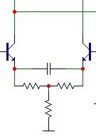
Thanks Nico... But why?? What will the effect of this have? Looks like it will cause the gain to drop as frequency increases??
Leigh
P.S C1 is not present on the realworld prototypes.. this was just added to improve THD at high freqs in the sim, i'll put this in later maybe when things are more stable. And just to clarify C8 and R21 are just to simulate a speaker load. C8 is not part of a filter but i keep it in to check for capacitive instabilities not that it has done me any good LOL
nitrate said:Thanks Nico... But why?? What will the effect of this have? Looks like it will cause the gain to drop as frequency increases??
Leigh
Degeneration resistors fixes hfe but affects dynamic characteristic. Capacitor shorts emitters at ac potential. About 100 - 470 uF needed. Try it and go for a beer.
Ciao
- Status
- This old topic is closed. If you want to reopen this topic, contact a moderator using the "Report Post" button.
- Home
- Amplifiers
- Solid State
- Oscillation woes....Help needed...