.model 2sa965 PNP(
+Is=4.956p
+ Xti=3
+ Eg=1.11
+ Vaf=100
+ Bf=156.1
+ Ise=4.957p
+ Ne=1.434
+ Ikf=3.085
+ Nk=1.053
+ Xtb=1.5
+ Var=100
+ Br=1.02
+ Isc=2.06n
+ Nc=1.35
+ Ikr=3.312
+ Rc=.5442
+ Cjc=2p
+ Mjc=.3333
+ Vjc=.75
+ Fc=.5
+Cje=5p
+ Mje=.3333
+ Vje=.75
+ Tr=10n
+ Tf=1.324n
+ Itf=1
+ Xtf=0
+Vtf=10)
.model 2SC2235 NPN(
+ IS=2.2874E-12
+ BF=193.91
+ VAF=100
+ IKF=1.4742
+ ISE=2.2874E-12
+ NE=1.3496
+ BR=3.5606
+ VAR=100
+ IKR=53.900E-3
+ ISC=21.348E-9
+ NC=1.9528
+ NK=.70855
+ RC=.22419
+ CJE=2.0000E-12
+ CJC=60.728E-12
+ MJC=.33333
+ TF=1.0969E-9
+ XTF=10
+ VTF=10
+ ITF=1
+ TR=10.000E-9)
.model 2SC5171 NPN(
+ IS=10.000E-15
+ BF=210
+ VAF=100
+ IKF=10.000E-3
+ XTB=1.5
+ BR=.1001
+ VAR=100
+ IKR=10.000E-3
+ ISC=10.000E-15
+ CJE=2.0000E-12
+ CJC=38.866E-12
+ MJC=.33333
+ TF=83.239E-12
+ XTF=10
+ VTF=10
+ ITF=1)
So far I failed to import any new model into PSpice Student - freeware- model lib. Is that feature disabled in the freeware version or am I doing something wrong?
Thanks.
Btw considering distortion in amplifiers I prefer results obtained
at a university about human audition. It does not matter that much how the value of THD is what matters for a favorable overall impression is that the energy of the harmonics decrease in a particular mathematical series.
Thanks.
Btw considering distortion in amplifiers I prefer results obtained
at a university about human audition. It does not matter that much how the value of THD is what matters for a favorable overall impression is that the energy of the harmonics decrease in a particular mathematical series.
any news so far? i'm also searching for them..i'm needing SPICE models for these bjts

thanks in advance
same for me, a 3-stage Amp, i need them as the last lacking models.
never seen spice models on any DS seen until now..
just these basic info's on 2SA1011 (and nothing for 2SC2344)
" ap_pnp_2SA1011_19930601 Basic Description: PNP Transistor, Part number: 2SA1011, Key parameters: Is=1E-14 Bf=100 Tf=2.274E-08 "
found on PNP BJT Models - ADS 2008 Update 1 -Agilent EEsof Documentation Center (you already know..)
maybe some equivalent model ?
the closest match i can find so far (and it's still not really that close) are devices with 30Mhz Ft. the A1011/C2344 devices have Ft's of 100Mhz. having fast devices is crucial in the APT-1. it has a triple darlington output stage and any compromise in the transistors has adverse effects on the stability.

tnx.... i'll extract the text and post it later today... that's exactly what i was looking for.... now if i could also find a good model for the MPSU10 and U60 devices.... the ones i have are "one-liners" with only 3 parameters... so i used other (actually pretty close) devices in their place... but the A1011 and C2344 devices were really difficult to work without...
yes, it worked!!!! now the amp model is stable with the original 25p compensation caps AND the feedback connection in it's proper place....
so here's what i added to standard.bjt:
these models are "lifted" from the first set of models, but leave out the lead strays in the .subckt part of the model
the second set of models has junction capacitances way out of whack
so here's what i added to standard.bjt:
Code:
.Model 2SA1011 PNP (IS=26.197F BF=137.502 NF=1.000 VAF=453.549 IKF=1.142 ISE=5.894F NE=1.200 BR=20.357 NR=1.000 VAR=20.000 IKR=0.143 ISC=26.197F NC=1.200 RB=6.720 IRB=0.750M RBM=1.680 RE=0.467 RC=1.400 CJE=48.000P VJE=0.700 MJE=0.400 TF=1.771N XTF=9.695 VTF=2.000 ITF=1.155 PTF=1.000 CJC=75.000P VJC=0.600 MJC=0.330 XCJC=0.650 TR=95.493N CJS=0.0 VJS=0.700 MJS=0.500 XTB=1.000 EG=1.110 XTI=4.000 KF=5.000F AF=1.000 FC=0.750
.Model 2SC2344 NPN (IS=26.197F BF=239.309 NF=1.000 VAF=453.549 IKF=1.155 ISE=3.368F NE=1.200 BR=20.357 NR=1.000 VAR=20.000 IKR=0.144 ISC=26.197F NC=1.200 RB=6.635 IRB=0.750M RBM=1.659 RE=0.160 RC=0.480 CJE=48.000P VJE=0.700 MJE=0.400 TF=1.398N XTF=9.623 VTF=2.000 ITF=1.171 PTF=1.000 CJC=45.000P VJC=0.600 MJC=0.330 XCJC=0.650 TR=95.493N CJS=0.0 VJS=0.700 MJS=0.500 XTB=1.000 EG=1.110 XTI=4.000 KF=5.000F AF=1.000 FC=0.750
these models are "lifted" from the first set of models, but leave out the lead strays in the .subckt part of the model
the second set of models has junction capacitances way out of whack
Last edited:
i saw your APT-1 files in the LTspice Group and i'm curious,yes, it worked!!!! now the amp model is stable with the original 25p compensation caps AND the feedback connection in it's proper place....
what is it? did you design it? it's rather complex, congratulations! ( too much for my capabilities
)what did you leave out, and wht's the purpose of this "subckt"part?these models are "lifted" from the first set of models, but leave out the lead strays in the .subckt part of the model
1st test example (with only one device) was provided by the author of the 1st model, using .model sintax, and it's missing of the same part
sorry, i can't understand "way out of whack", neither GoogleTranslate.it ..the second set of models has junction capacitances way out of whack
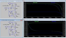
i see that CJc and Cje values are quite slower in 1st model than in 2nd, and (see my screenshot) AC analysis are acting different, with a strange "band-pass" behaviour on the 2nd model..or it's not strange?
did you read my .htm file, showing how was 1st-model born?I find it strange that the models have so many identical values. The only thing that is different is NPN vs PNP. The real world of Spice characterization is just not like that. I wouldn't trust them for anything other than basic functionality.
any comment or suggestion about?
this is the 2nd model set (don't know how was born, except from data sheet graphs)
Code:
.model 2SA1011 PNP(Is=6.734p Eg=1.11 Vaf=100 Bf=106.7 Ise=6.755p Ne=1.328 Ikf=2.481 Nk=.8564 Xtb=1.5 Br=8.268 Isc=6.734p Nc=1.167 Ikr=.9435 Rc=1.155 Cjc=483.8p Mjc=.3806 Vjc=6.248m Cje=500p Tr=181.1n Tf=1.603n Itf=1.08 Xtf=4.227 Vtf=10 Vceo=160 Icrating=1.5 mfg=Sanyo)
.model 2SC2344 NPN(Is=26.94p Eg=1.11 Vaf=100 Bf=333.1 Ise=192.6p Ne=1.488 Ikf=2.436 Nk=1.017 Xtb=1.5 Br=216.9 Isc=241.8n Nc=2.259 Ikr=482.5 Rc=.6049 Cjc=250.5p Mjc=.4004 Vjc=11.36m Cje=250p Tr=33.47n Tf=1.526n Itf=13.13 Xtf=41.6 Vtf=10 Vceo=160 Icrating=1.5 mfg=Sanyo)
Attachments
Last edited:
"out of whack" means "is very wrong". it's an "americanism" that has it's roots in the fact that the old rotary TV tuners often got dust or oxidation in the drum contacts. the tuner would develop intermittent faults that could be temporarily fixed by whacking the side of the TV set. so when the TV started getting poor reception or had a blank screen, it was "out of whack"
the CJC and CJE values for the second set of models is around 350pf which is very high, the 45pf or so in the first model is closer to the truth.
no i did not design the APT-1, Tom Holman (THX, Audyessy) did back in the late 70's. i worked there for 5 years as an amplifier tech.
the .subckt part of the first two models is the stray lead inductance and capacitance of the TO-220 package. the .model portion of the transistor models can be added to standard.bjt and this adds the two devices to the drop down list of transistors in the Change Transistor dialog box.
the models were generated from the parameter dialog, but reading through the models, they aren't completely identical.
the "bandpass" that you are seeing is because of the 10m cap in the test circuit
- Status
- This old topic is closed. If you want to reopen this topic, contact a moderator using the "Report Post" button.
- Home
- Amplifiers
- Solid State
- 2SA1011/2SC2344 models needed