I have searched these forums and the web, and I have a general "idea" as to how a grounded bridge amplifier works (I understand the Crown Audio white paper regarding the grounded bridge).
According to Dynacord (I.E. the P3000), the output stage is a "Class H 3 stage grounded bridge" topology. What exactly does this mean, as compared to a regular "grounded bridge" topology? I looked for any white papers from Dynacord, but I could not find any regarding this proprietary output stage.
According to Dynacord (I.E. the P3000), the output stage is a "Class H 3 stage grounded bridge" topology. What exactly does this mean, as compared to a regular "grounded bridge" topology? I looked for any white papers from Dynacord, but I could not find any regarding this proprietary output stage.
In Class-H amps with Grounded Bridge Topology we have 3 choices to choose for:
1. Monorail Switching like in QSC PL6.0II amp. Switching from Lower Tier to Higher[Tier might ranges from 2 to 4 steps] is made using only one side of rail, but excitation takes place for both polarity of signals.
2. Series-Parallel technique is like configuring the 2 isolated supply voltage sources in Series for greater voltage swing and for low current te voltage sources are paralleled, its a Pseudo Class-H.
3. Regular Class-H switching which is used by Dynacord intheir POWER H series, it uses switching for both polarity of signals along with individual rail switch for Each Quadrant of the bridge.
Monorail is more advantageous of all. Its a low cost, low part count & high reliability topology. For single step Class-G is best way in monorail switching, for more steps Class-H wins.")
1. Monorail Switching like in QSC PL6.0II amp. Switching from Lower Tier to Higher[Tier might ranges from 2 to 4 steps] is made using only one side of rail, but excitation takes place for both polarity of signals.
2. Series-Parallel technique is like configuring the 2 isolated supply voltage sources in Series for greater voltage swing and for low current te voltage sources are paralleled, its a Pseudo Class-H.
3. Regular Class-H switching which is used by Dynacord intheir POWER H series, it uses switching for both polarity of signals along with individual rail switch for Each Quadrant of the bridge.
Monorail is more advantageous of all. Its a low cost, low part count & high reliability topology. For single step Class-G is best way in monorail switching, for more steps Class-H wins.
After reading the Crown white paper on the grounded bridge topology again,
There are two "pairs" of "output devices" connected to the load, one pair (let's say an NPN and a PNP transistor) that drives the speaker itself, and the other pair drives the "ground" so as to adjust the floating voltage power supply to the correct level.
Can I say that the power dissipated in the output stage is twice that of a regular, conventional output stage? I see that in a grounded bridge configuration, the output current will always flow through two output devices, either through the load driving NPN and the ground driving PNP, or through the load driving PNP and the ground driving NPN.
Am I correct in saying this?
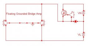
The power dissipated in a grounded bridge is not any worse than any other "bridge". It's only slightly more than a single-ended topology. It just trades voltage for current, and has half the voltage on the transistors. "Grounded" bridge is advantageous in that two channels are again "bridgeable" because the supplies are independent.
If you're going to switch all four quadrants of a grounded bridge you may as well just put both secondaries in series, cascode the output stage and just switch like a normal amp.
If you're going to switch all four quadrants of a grounded bridge you may as well just put both secondaries in series, cascode the output stage and just switch like a normal amp.
DJK:
Can you tell us more?
I started a similar topic: Can some one explain me this amp?
http://www.diyaudio.com/forums/showthread.php?s=&threadid=114431
There was not much reaction allthough it gave me a bit of insight.
Maybe here there is more to learn.
thanks,
Tarzan
Can you tell us more?
I started a similar topic: Can some one explain me this amp?
http://www.diyaudio.com/forums/showthread.php?s=&threadid=114431
There was not much reaction allthough it gave me a bit of insight.
Maybe here there is more to learn.
thanks,
Tarzan
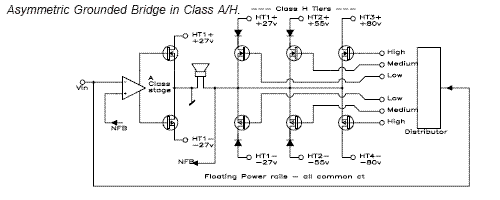
djk: thank you for the post - that is a very good pic showing the concept
I still have a question:
Maybe I'm just not "seeing" it, but for the class A amplifier, why is it only +/- 27V? Wouldn't this cause clipping if the other side of the bridge is driving the speaker at, say, +50V?
I can see how the right side is a rail switching amplifier --> Does this mean that the +/- 27V, +/- 55V, and +/- 80V rails are sharing a common "floating" ground?
The Crown VZ5000 and vz3600 use the saturated switch, National Semiconductor was issued a patent on the linear modulated method.
Using a PWM top rail modulated by the audio is the basis of the old Sunfire subwoofer amp (and the BASH amps too).
Sandman proposed a bridge amp scheme circa 1971 that has a small high quality amp (A2) controling a larger quick-and-dirty one (A1).
The first commercial version of the asymetric bridge amp I saw was the old Yamaha B2X, the class A side ran on ±6V, the class AB side on ±63V.
The thumbnail drawing I posted of the asymetric class A design was from BSS, a pro sound amplifier.
One question that I have failed to ask, and I think it would help in understanding the grounded bridge concept:
I am assuming that, in most grounded bridge amplifiers, the amp still resembles a basic "three stage" conventional amplifier (input differential pair, VAS, and then the grounded bridge output stage).
==> What supply voltages are needed in the first and second stages? For instance, if a grounded bridge amp has a maximum voltage supply of 75V on its output devices (floating, so the load could either be +75V or -75V maximum), then does this mean that the input stage and VAS stage should be powered from a conventional +/- 75V supply to prevent clipping?
-------------------
==> Sandman proposed a bridge amp scheme circa 1971 that has a small high quality amp (A2) controlling a larger quick-and-dirty one (A1).
Yes, I *think* that this was the beginning of the SMALA amp (switch-mode amplifier linearly assisted), where the class-D amplifier (high efficiency, not so great distortion) supplies the majority of the current, and the "linear assistance" class A (or AB) amplifier provides the small correction current to smooth out the distortion. These currents add before reaching the load, and theoretically, the result is a high efficiency, better linearity amp. Correct me if I am wrong in my assertion here.
rtarbell said:
==> What supply voltages are needed in the first and second stages? For instance, if a grounded bridge amp has a maximum voltage supply of 75V on its output devices (floating, so the load could either be +75V or -75V maximum), then does this mean that the input stage and VAS stage should be powered from a conventional +/- 75V supply to prevent clipping?
The VAS on the high side runs off the floating supply. The low side doesn't need a VAS, the output of an op amp on +/-15 (referenced to the ground it's driving) is all that's needed - just like a QSC amp.
==> Sandman proposed a bridge amp scheme circa 1971 that has a small high quality amp (A2) controlling a larger quick-and-dirty one (A1).
Yes, I *think* that this was the beginning of the SMALA amp (switch-mode amplifier linearly assisted), where the class-D amplifier (high efficiency, not so great distortion) supplies the majority of the current, and the "linear assistance" class A (or AB) amplifier provides the small correction current to smooth out the distortion. These currents add before reaching the load, and theoretically, the result is a high efficiency, better linearity amp. Correct me if I am wrong in my assertion here.
The low side can have fairly high distortion because it drives the "ground" which is the same as the input ground. Distortion products become a common-mode signal, and in effect, show up on the floating supply. If the high side amp has good PSRR, it rejects it. Some of Crown's amps have a "dirtier" low side amp (especially the bias circuit which won't track as well over temp as what they use on the high side).
wg_ski said:
The low side can have fairly high distortion because it drives the "ground" which is the same as the input ground. Distortion products become a common-mode signal, and in effect, show up on the floating supply. If the high side amp has good PSRR, it rejects it. Some of Crown's amps have a "dirtier" low side amp (especially the bias circuit which won't track as well over temp as what they use on the high side).
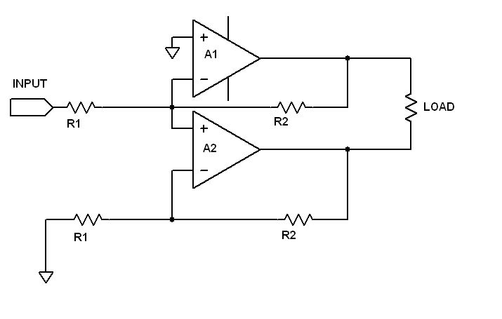
Seperate amp for each half bridge in a GB Amp is followed by Crown, which is not good in terms of sonics
but if you go for compound GB amp using true differential IN-differential OUT, then the result is awesome, i have designed it using Diamond Differential input and Balanced Grounded Bridge output along with 2 Step Class-H........
- Status
- This old topic is closed. If you want to reopen this topic, contact a moderator using the "Report Post" button.
- Home
- Amplifiers
- Solid State
- Dynacord "3-stage grounded bridge" amp