I have noticed tha the transformer based passive preamps have been popular and are getting good reviews.
Also som of the potentiometer based units are getting good reviews, but they have traditionally been claimed for reducing dynamics?
I wonder where the biggest limitations with passive potentiometers are?
-Source driving cable and potentiometer?
-Potmeter driving cable and input impedance of power amplifier
-Both
It will all depend on the different impedance levels off cource, but what potentiometer values are recomended?
For driving 10K input?
For driving 200K input?
Why i trafos better?
Hi,
transformers are imo not better than resistive solutions, but vice virsa, when done properly. One big drawback is that good transformers are quite expensive and just allow for a couple of volume steps. Nice thing is that there will be no galvanic coupling of devices.
Simple potentiometers are not the right stuff to use, because of the high and changing output impedance. Typical sources are able to drive loads down to 1kOhms and even below. So You don´t need the constant input impedance the potentimeter shows. A changing input resistance of a resistive network is therefore no problem as long as its value is high enough. What You need is a rather lowish and constant value of the output impedance. Therefore You need other networks with at least 3 resistors per step.
Such a network doesn´t leave anything to wish for sonically and outperforms transformer-solutions, as well as any active solution.
jauu
Calvin
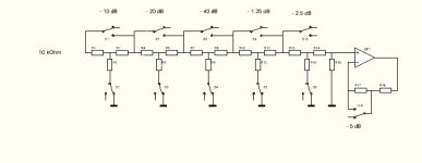
This is an "almost passive" preamp.
The attenuator is configured such that input impedance is constant 10 kOhms for all attenuations and output impedance is constant 3 kOhm for all attenuations except 0 dB.
It allows for attenuation in 1.25 dB steps.
Relays are encapsulated nitrogen-filled Teledyne. The amp is in use for about 20 years the relays are still doing perfectly well.
The bipolar chip opamp was later replaced by a discrete Aikido replica with 2N5196 matched n channel JFET pair and BUZ22 Mosfet.
It can drive 3 volts rms into 1 kOhm without distortion.
Dieter F.
Attachments
Calvin said:Therefore You need other networks with at least 3 resistors per step.
Such a network doesn´t leave anything to wish for sonically and outperforms transformer-solutions, as well as any active solution.
Calvin, well said.
I've build active preamps with LM4562 chips but really...there is nothing like a passive preamp with decent stepper att.'s.
Dynamics are absolutely no problem with a passive. The so called "increased dynamics" with an active is mostly due to some kind of more bass and is a kind of distortion whereas a passive is so utterly clean that it looks like it is less dynamic.
Use 10k steppers with low impedance dc coupled output sources and reasonably high impedance dc coupled power amps. like the f.i. the UCD's.
Hi,
if you are going to passive pot attenuation then start with a low source impedance.
Let's start from your source:
Rs~=100r,
Pot ~=20Times Rs, gives pot~=2k.
Can your source drive 2k0 to normal signal levels?
Can the source drive the 2k0 to somewhere between +12dB to +20dB above normal signal levels?
If yes to both, then proceed.
The maximum output impedance of the pot is [Rs+potvalue]/4=[100+2000]/4=525r
The Zin of the next stage should be ~=20Times maximum pot output impedance. i.e Zin~=20*525~=10k.
If your source impedance is different from 100r then scale all the values accordingly.
Now calculate the DC blocking capacitors required in the source and in the power amp to suit your chosen frequency response. These are liable to be quite large and may need to be electrolytic//polyplastic.
Now calculate the maximum stray capacitances that the cables and PCB layouts will add. This effectively lowers the input impedance seen by the previous stage and raises the current capability required of the source to drive the subsequent stages.
The lowish impedances of the example will tolerate quite high values of pF. if you increase your source impedance then you risk losing some of the high frequency range due to unavoidable capacitances of passive pots.
AndrewT, please remind me about the low pass filter created by the high impedance and cable capacitance.
I assume it is a one-pole filter with a corner at 1/ (2*pi*R*C)
The C would be the total capacitance of the cable (mainly)
and the R would (mostly) be 1/4 Pot value (asuming worst case where the pot is positioned half-way.
Did I get it right?
I assume it is a one-pole filter with a corner at 1/ (2*pi*R*C)
The C would be the total capacitance of the cable (mainly)
and the R would (mostly) be 1/4 Pot value (asuming worst case where the pot is positioned half-way.
Did I get it right?
yes,
series resistance/impedance before the Capacitance and total capacitance after the series impedance.
But there is a second low pass filter before the pot as well, but it's frequency is likely to be considerably higher if short cables are used.
If long cables between source and pot and short cables/low stray capacitance after the pot then the two turnover frequencies could be similar, resulting in a Bessel (Q=0.5) turn over characteristic which has a slow attenuation rate below turn over frequency. You need to ensure this stays much higher than your pass band requirement.
I wonder if a target f-3dB >= 500kHz is worth aiming for both low pass filters?
Any comment?
Thomas
its been 20 years and I am messy but I found a document that has the values of the first -10 dB step attenuators
R1 6800 Ohms
R2 4700 Ohms
R3 230 Ohms
R4 8760 Ohms
R5 1500 Ohms
R6 3300 Ohms
R7 10000 Ohms
R11 150 Ohms
R12 4700 Ohms
The attenuator is terminated with 10051 Ohms
The attenuation was measured with HP RF voltmeter only the -50 dB deviates by 0.1 dB as it yields -50.1 dB attenuation.
All other errors are less 0.1 dB.
The input selection is also accomplished with Teledyne military spec encapsulated relays. A push pull emitter follower ensures impedance of less 10 Ohms.
I cannot find docu for the other resistor values nor of the PC board layout this is supposed to sit on a 5 inch floppy disk which cannot be read by any existing PC excpet perhaps in Siberia East.
The device is built in a Mu metal case the power supplies for the Opamp and the logic ( an up down counter ) are external.
Replacing the power supply with a set of 2 times 2 7.5 volts NiCad packs made great audible improvement and is highly recommended.
Should I find more docum ( not very likely ) I will post it.
Dieter F.
- Status
- This old topic is closed. If you want to reopen this topic, contact a moderator using the "Report Post" button.
- Home
- Amplifiers
- Solid State
- Passive preamp?