Recently I undertook a rebuild, complete with a new chassis of the old AEM 6010 series preamplifier.
I am delighted with the results, with the exception of a low level hum when the phono stage is selected.
The hum appears to be at a constant level, and despite trying alternative earthing / grounding arrangements, I am unable to locate the problem.
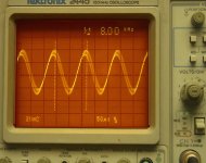
I have attached a picture of a CRO screen shot (it’s the best I can do, thanks to Photoshop) of the output waveform.
The waveform as shown is at 8 khz with an input voltage of 5mV. The waveform has been taken form the normal preamp output.
All of the high level inputs are perfect with no problems.
As you can see, the waveform is nice and clean on one side, but becomes dirty on the downward leg of the cycle.
I have swept the frequency from 20 hz to 20 khz, and the dirty waveform first appears at about 3.5 khz, and gets progressively worse.
However, the “rise” section of the waveform is always clean.
Unfortunately my knowledge of interpreting CRO results such as this is somewhat limited.
I would be very grateful for any assistance, or if anyone could shed any light on this matter.
Thanks in advance.
Regards
George.
I am delighted with the results, with the exception of a low level hum when the phono stage is selected.
The hum appears to be at a constant level, and despite trying alternative earthing / grounding arrangements, I am unable to locate the problem.
I have attached a picture of a CRO screen shot (it’s the best I can do, thanks to Photoshop) of the output waveform.
The waveform as shown is at 8 khz with an input voltage of 5mV. The waveform has been taken form the normal preamp output.
All of the high level inputs are perfect with no problems.
As you can see, the waveform is nice and clean on one side, but becomes dirty on the downward leg of the cycle.
I have swept the frequency from 20 hz to 20 khz, and the dirty waveform first appears at about 3.5 khz, and gets progressively worse.
However, the “rise” section of the waveform is always clean.
Unfortunately my knowledge of interpreting CRO results such as this is somewhat limited.
I would be very grateful for any assistance, or if anyone could shed any light on this matter.
Thanks in advance.
Regards
George.
Attachments
George, Your screen shot looks like modulation hum.Turn down the timebase on your scope i.e. make the sweep speed longer and I think you will see your 50/60 Hz signal on top of your test tone.(Your 8Khz signal is almost certainly "clean" it's just that you have an unwanted signal along with it).Try shorting the phono input to preamp, that is to say, if it uses phono sockets get two phono plugs and short center pin to ground.Can you hear any hum ? With your scope at it,s most sensitive e.g. 1mv/div can you measure any hum/noise at output.It could be a noisy supply rail to the phono stage.Can you measure any ripple on the d.c. supply feeding it.Is the hum at line frequency (50 or 60 Hz or is it more like a harsh buzz at twice that at 100 or 120 Hz)
Regards
Karl
Regards
Karl
Hi Karl
Thank you very much for your comments. They are greatly appreciated.
Your thoughts regarding the supply rails could definately be the problem, and yes I can measure ripple.
The main filter caps that are being used for the supply to the phono board are quite old (approximately 17 years). I used the same ones out of the original build to save a few dollars.
Looks like that was a bad idea.
I will investigate further.
Once again, thanks for helping me.
Regards
George.
Power supply measurements
I have taken a closer look at the DC power supply rails that feed the phono stage board, and these are the results.
I must admit, the waveform is not quite what I expected, when referencing one of my electronics textbooks.
The rectifier is a full wave bridge rectifier, so the 100hz would appear to me to be correct.
Is my assumption that the horizontal component of the waveform is the charging of the reservoir capacitors?
The supply rails are +/- 35v. The top trace is the +35v rail, and shows an AC component of about 65mV, and the bottom trace is the –35v rail, and shows an AC component of about 20mV.
The measurements we taken with the power supply under full load.
The problem I have is that the waveform is not what I expected, and to me it appears that there is a problem.
At the very least, I would have expected the AC component to be the same for both rails.
I am not asking to have the problem solved for me, but would appreciate if someone could shed some light so I may learn.
My difficulty is that what the scope is telling me is not what my understanding of my textbook is.
I also suspect that this is the reason for the hum.
Regards
George.
Attachments
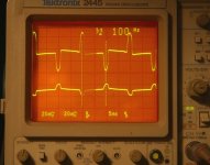
What you have there is a waveform that indicates charging currents- the spikes are synchronous with the peaks of the AC waveform, where the rectifiers are able to charge the reservoir caps. Their appearance suggests some power supply grounding problems or a non-optimal choice of where to put your scope ground clip.
If you can post a schematic of the power supply, someone might be able to point out the spots to look for. If you have a photo showing how the wiring is set up, that would be even better.
If you can post a schematic of the power supply, someone might be able to point out the spots to look for. If you have a photo showing how the wiring is set up, that would be even better.
power supply pic
Hi Sy.
Thank you for your assistance.
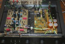
Here is a pic of the power supply.
My probes were taking the measurements at the power input of the phono board.
I will post some pics of the actual preap as soon as I get a chance.
Regards
George.
Hi Sy.
Thank you for your assistance.
Here is a pic of the power supply.
My probes were taking the measurements at the power input of the phono board.
I will post some pics of the actual preap as soon as I get a chance.
Regards
George.
Attachments
Looking down the 0V (ground line), make sure that the first five connections (especially) all are made at a single point and that nothing is connected between that point and the power supply returns (the wires coming from the connectors). Those appear to be the power supply returns and the reservoir caps.
Hi again Sy.
Thank you for your comment on the earthing, as this has stirred my memory somewhat.
I vaguely remember going back many years ago when i built this preamp for the first time, that I had earth loops / hum problems.
Whilst im not 100% sure, I think that I disconnected the final earth connection from the 0V line.
As the layout currently stands, 0V forms the reference point and the signal earth lines are isolated from each other until they reach the power supply 0V lines (chasis sockets). This point does not return to a traditional earth to the power / wall supply mains.
The noise that I hear this time is not what I would call a traditional 50hz hum. Whilst is is extremely difficult to discribe, it is more like a low level (amplitude speaking) buzz.
Maybe i am correct here, as the spikes as shown on my second scope photo are 100hz apart.
Regards
George.
Here is an internal view of the preamplifier.
The layout basically is as follows:
1.The power supply, muting and line stage is on the right
2.The phono stage is on the left.
3.On the rear of the RHS side, is the main receptacle for the AC power in which is obviously being derived from an external AC PSU.
4.The main AC in is at the front of the power supply board.
I have left the probes in place, so it can be seen as to where I was taking the voltage measurements, which is at the power input of the phono stage.
Regards
George.
Attachments
Hi George, Earlier on I asked was it a hum or a buzz(Harsh sounding), as this is a big clue as to it's origin.Your circuit shows a +/- 15 volt supply, (the 7815/7915 regulators.Do these feed just the phono amp ? Anyway first off you need to be sure that all rails are clean.You have to use the correct grounds when making measurements like this, also if your 'scope is earthed (mains earth), as well as the amp this can cause false readings.Is the amp earthed through the P.S.U. ? To check the rails connect probe ground to main signal ground on the phono P.C.B. and measure ripple on +15 -15, & +35 -35 . It should be "unmeasurable".Did you try it with the inputs shorted by the way, did the hum decrease. ? Silly question, is the hum only present when installed as part of full system or is it present with just the preamp on the bench (with those inputs shorted). Remember that correct earthing and using the correct earth is EVERYTHING when trying to eliminate a problem like this.Make sure there are no multiple earth points e.g. P.S.U. grounds from the reservoir caps and signal grounds connected to the chassis.
Those parallel 2200 mfd caps look a bit over the top for a preamp, the problem is that the more capacitance you add the shorter the "conduction angle" of the charging pulses in the bridge rectifier.These can be momentarily in the 10,s of amps range and consequently generate a ripple component even across a thick piece of wire or P.C.B. track.Hard to believe but just 470mfd could improve it a lot if there is a problem with grounding.Those large values also increase the radiated hum field from the mains transformer due to those massive charging currents.If layout is O.K. though this should'nt' be the problem.
Let us know how you get on and remember EARTHING,EARTHING EARTHING.
Regards
Karl
Mooly said:Hi George, Earlier on I asked was it a hum or a buzz(Harsh sounding), as this is a big clue as to it's origin.Your circuit shows a +/- 15 volt supply, (the 7815/7915 regulators.Do these feed just the phono amp ? Anyway first off you need to be sure that all rails are clean.You have to use the correct grounds when making measurements like this, also if your 'scope is earthed (mains earth), as well as the amp this can cause false readings.Is the amp earthed through the P.S.U. ? To check the rails connect probe ground to main signal ground on the phono P.C.B. and measure ripple on +15 -15, & +35 -35 .
Hi Karl.
Thank you for your response.
Your comments have certainly given me some more ideas to try out later tonight.
The noise is definately more of a low level buzz rather than a hum.
The buzz is present when the preamp is connected into the system, when the phono is selected.
The only supply to the phono board is the +/- 35V. the 15V rails are for the high level stage.
I have not yet tried the shorting of the phono plugs, as I have been concentrating on the PSU measurements.
Tonight I will re examine the earthing, and try to find a "clean" earth and re-examine the results on the scope.
PS those electros on the phono board are a secondary filtering of the 35V rails.
The original specification called for 1000uF capacitors, but I used 2200uF, thinking that more would be better.
Thank you for taking the time to assist me.
I will post my results later on tonight.
Regards
George.
Mooly said:
Let us know how you get on and remember EARTHING,EARTHING EARTHING.
... and Gordy chips in with his standard answer...
George, you may have seen these references already, but if not I recommend that you spend an hour having a read.
http://www.gbaudio.co.uk/data/ground.htm
Ground loops
http://www.tcaas.btinternet.co.uk/jlhearthing.htm
Grounding
http://sound.westhost.com/earthing.htm
Grounding
http://www.dself.dsl.pipex.com/ampi.../balanced.htm#7
Balancing and grounding
http://rane.com/note151.html
Grounding and shielding from Rane
http://rane.com/note110.html
Interconnection from Rane
http://www.elecdesign.com/Articles/...cleID=5944&pg=1
Grounding in ADCs
http://peufeu.free.fr/audio/extremi...mplement_2.html
Supply and ground in digital systems
Good luck.
GV, the picture didn't help as much as I would have liked- too much hidden. And it's possible that the ground layout on the circuit boards is poor, which will not be trivial to fix.
The sort of ground loops that are caused by earth grounding aren't the issue here- this noise appears to be from power supply grounding and the strong possibility that grounds from other parts of the circuit are connected in different spots within the high-current loop between the rectifiers and smoothing caps. I'd pull the PS board and examine how the grounds are applied.
The sort of ground loops that are caused by earth grounding aren't the issue here- this noise appears to be from power supply grounding and the strong possibility that grounds from other parts of the circuit are connected in different spots within the high-current loop between the rectifiers and smoothing caps. I'd pull the PS board and examine how the grounds are applied.
Hi,
I agree with Sy, thinking this is a PSU problem.
It could be caused by bad wiring or bad PCB or bad components.
Powering up the PSU alone and testing/measuring how well it works with various loads on it may be enlightening.
Then check that the installation matches the bench results.
I agree with Sy, thinking this is a PSU problem.
It could be caused by bad wiring or bad PCB or bad components.
Powering up the PSU alone and testing/measuring how well it works with various loads on it may be enlightening.
Then check that the installation matches the bench results.
Hi Karl, Sy, Andrew, Moody and all others.
Once again, thank you very much for your assistance.
Last night, I tried to locate an alternative earth / ground location for some CRO measurements.
This did not bear any fruit.
I also tried alternative wiring / grounding arrangements, and this did not alleveiate the problem.
AS you gentlemen have suggested, I am now more than ever convinced that the problem is within the PSU.
Tomorrow night I will strip the preamp down, and test the PSU in isolation, with some resistive loads. I will record the measurements, and photograph critical CRO screen shots.
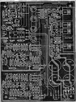
As i mentioned at the start of the thread, this preamp is a complete rebuild, which includes the fabrication of a new PCB which contains the PSU, high level and muting.
I did not make any major alterations to the track layout, especially the grounding and main filter cap area. The only area where i did a substantial track redesign was for the 4 voltage regulators / pass transistors.
Atatched is a copy of the original board layout, as published by AEM.
I will post a copy of my layout very soon
Thank you
Regards
George.
Once again, thank you very much for your assistance.
Last night, I tried to locate an alternative earth / ground location for some CRO measurements.
This did not bear any fruit.
I also tried alternative wiring / grounding arrangements, and this did not alleveiate the problem.
AS you gentlemen have suggested, I am now more than ever convinced that the problem is within the PSU.
Tomorrow night I will strip the preamp down, and test the PSU in isolation, with some resistive loads. I will record the measurements, and photograph critical CRO screen shots.
As i mentioned at the start of the thread, this preamp is a complete rebuild, which includes the fabrication of a new PCB which contains the PSU, high level and muting.
I did not make any major alterations to the track layout, especially the grounding and main filter cap area. The only area where i did a substantial track redesign was for the 4 voltage regulators / pass transistors.
Atatched is a copy of the original board layout, as published by AEM.
I will post a copy of my layout very soon
Thank you
Regards
George.
Attachments
Progress Report.
After three nights of investigation work, I am now more convinced that ever that the problem lies within the power supply.
Unfortunately, despite my best efforts, I am still unable to resolve the problem.
As mentioned in one of my previous responses, I did alter the circuit layout, but only the pass transistors / regulator area. The 0V layout remained essentially the same.
This is what I tried:
1. Looked at different sampling points for the probes.
2.Disconnected the phono stage and loaded up the power supply with a resistive load.
3.Tried different earthing techniques
4. Replaced the main filter caps.
5. Changed the regulators and pass transistors
After all of this, I did manage to get a reduction in the charge peaks, but that is about it. The problem still persists.
I suspect that the problem is in my modified board layout. I have not given up just yet. This weekend I will be building a new external power supply, and conducting further tests.
My sincere thanks to all that have offered advice and assistance. It is greatly appreciated.
I will post my next round of results as soon as possible.
Regards,
George.
- Status
- This old topic is closed. If you want to reopen this topic, contact a moderator using the "Report Post" button.
- Home
- Amplifiers
- Solid State
- Preamp help – Interpreting the results.