Hi everybody,
I got some LSK389C dual jfets today from Linear Systems because they will ship you samples for free. I wanted to throw them into a SRPP type stage because I think its cool looking.
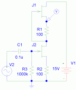
Attached below is the picture of how I set it up. The resistors I used were 150 ohm. I matched the resistors within +-0.2 ohms on my meter. This gave a voltage at the probe point of 9.7 volts, which it should be ~8.1 volts based off a sim (not real world). So with some better matching resistors or a pot instead of a resistor in one place, it would come closer to the ~8.1 volts. I put in a 6.4mV signal and got a 750mV signal out for a total gain of 117. Not to shabby. From the sim these seem to be pretty linear setups right until they clip.
So what kind of solid state output stage could a guy (or girl I guess) use with this that would possibly, but not necessarily have some resemblance to a tube output stage? I found that this can't be dc coupled to the next stage, it must have a capacitor on the output.
I got some LSK389C dual jfets today from Linear Systems because they will ship you samples for free. I wanted to throw them into a SRPP type stage because I think its cool looking.
Attached below is the picture of how I set it up. The resistors I used were 150 ohm. I matched the resistors within +-0.2 ohms on my meter. This gave a voltage at the probe point of 9.7 volts, which it should be ~8.1 volts based off a sim (not real world). So with some better matching resistors or a pot instead of a resistor in one place, it would come closer to the ~8.1 volts. I put in a 6.4mV signal and got a 750mV signal out for a total gain of 117. Not to shabby. From the sim these seem to be pretty linear setups right until they clip.
So what kind of solid state output stage could a guy (or girl I guess) use with this that would possibly, but not necessarily have some resemblance to a tube output stage? I found that this can't be dc coupled to the next stage, it must have a capacitor on the output.
Attachments
You could try the Aikido with Jfet's. Bet it would be awesome.
http://www.tubecad.com/2005/July/blog0051.htm
http://www.tubecad.com/2005/July/blog0051.htm
Hi guys,
Thanks for the post on the Akido amp dshortt9. I have not read through it yet but took some of the ideas from the schematic and put them to use. I am not overly familiar with FET type transistors, so I used bipolars on the output.
I built it up with a emitter follower loaded with a constant current source. I will probably use a LED to bias the ccs transistor. Right before the onset of clipping from the current side of things, the THD is simming out to 2.81%. The diagram of how I have it set up is shown as well as the harmonic distribution. I think I will give this thing a wirl in building it up. It will take some time though.
What do you guys think?
Thanks for the help all.
Attachments
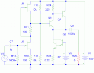
Thats kind of what I was thinking. The input signal is 300mV to get this level. The voltage gain can be changed by lowering or increasing the resistance of R13 and R14. I find it interesting as well that if the current running through the ouput stage is increased by 1 amp, the THD increases to 4.5% but the harmonic distribution looks even better. Most of the harmonic energy is in the 2nd harmonic and it seems to only extend to the 5th harmonic, then it is almost gone. I shall build this this week hopefully and see how it sounds.
The load could be connected to either supply rail.
Why did you choose to connect it to the negative rather than the positive?
I would try both alternatives and decide on sound quality which is better.
I think I know which might be better, but I have only ever built one single ended amp, for headphones, and didn't like the result.
Why did you choose to connect it to the negative rather than the positive?
I would try both alternatives and decide on sound quality which is better.
I think I know which might be better, but I have only ever built one single ended amp, for headphones, and didn't like the result.
Hi Andrew,
I choose the ground rail simply because we were always taught in school to connect the load to ground. I will try both and see if it sounds different.
Which one do you think is better? I have seen both ways on different amps. Is there any reason that one may sound better than the other? If the PSRR of an amp is good, I would think the ground rail would be the logical choice if it is wired properly so it is clean. What ever noise or ripple is on the positive line would get sent down the speaker.
Though one should have a clean positive line in this case since the PSRR is very low (don't think there is any rejection).
So I built this up with a darlington output transistor (tip120) with a darlington again used in the ccs. I put a 1k resistor from the positive rail to the point were the gate of the top one is connected to the drain of the bottom one, and then a 1k resistor from that point to ground. The point of this was to help drive that point back up to 1/2 Vc when the darlington transistor was connected as well as it brings the gain of the SRPP down a lot.
It sounds good to me. I can't tell any difference between connecting the output capacitor to the positive or ground rail, but my source is a mickey mouse cd player and my speaker is a 8 inch unit from a cheap guitar amp.
So Andrew, now that I have tried it and haven't heard any difference, do you hear a difference when you do it? I would imagine it is more noticeable on a better system than what I was trying it on. What is your preference for where the capacitor is connected?
Hi,
I gave up on my single ended about ten years ago and have not returned to that yet.
The speaker connection to the positive rail gives a true constant current draw on the supply as the signal changes. This can help remove some PSU artifacts from the output and can sound a little different, not necessarily better.
When the speaker is connected to the negative the change in current draw on the supply goes from near zero amps to double the quiescent bias current and causes severe ripple in the supply rails when the signal becomes significant. Do not believe the folk that tell you ClasssA is constant current, they know not what they are talking about. Only a very few ClassA topologies achieve constant current with signal change.
How do you achieve silent power up?
My power supply was outputting only 8 volts to get the 1 amp bias that the unit was set up for. This was a different class a stage that I build to run on +-10 volt rails. So the voltage at the output where the cap goes to the speaker is 3.8 volts when I measured it, thus there was not much voltage change there to make a bump. I didn't hear any thump anyways.
I checked in some sims about the constant current pull on the power supply you were talking about. Its true and seems like a good way of taking the variable load off of the power supply. With the load going to ground, the supplys current is increasing and decreasing with the music which would be constantly changing the supply ripple, while connecting the load to the positive supply causes the load current on it to be constant, thus causing the supply ripple to be constant. Thank you for telling me that information. I think that is a very neat thing to know about class a amps.
- Status
- This old topic is closed. If you want to reopen this topic, contact a moderator using the "Report Post" button.
- Home
- Amplifiers
- Solid State
- SRPP with FETS, what output stage?