Only truly experienced (and unfortunately very few) developers (like Quad) achieve a design of such triple stages without any oscillation under any load condition.
I want to have basic articles about such three stage super ß quasi complementary stages. Who knows more about this?
.
Check out the thread Class B w/o crossover distortion.
The Vish topology discussed is a derivate of the Quad 303 and has very nice properties but also some catastrophic disadvantages.
These are avoided in Quad 303 as the Rush cascode has current feedback to the emitter but at the expense of crossover distortion.
However each Quad triple cascade can be made always conducting and be still class B if one places a fast switching phase splitter in front of the two triples. If the switch switches at exactly zero-cross of the signal that would yield a perfectly stable crossover-distortion free class B amp.
About this address perhaps there is a complete Equa schematic available:
Audioclub Oost Brabant, clubavonden
I want to have basic articles about such three stage super ß quasi complementary stages. Who knows more about this?
I know too few English keywords therefore. I recall, that I have read some years ago a JAES article. But I don't know if it was the main topic.
In the meantime I have find this:
QuadTriple, Harman's T-Circuit, Triple Cascade, Elektor's EQUIN
http://www.diyaudio.com/forums/solid-state/160285-class-b-w-o-crossover-distortion-1975-a.html
Harmans T-Circuit: "An Ultra-Low Distortion Direct-Current Amplifier" from the author
BART N. LOCANTHI (James B. Lansing Sound, Inc.)
http://www.harman.com/EN-US/OurComp...ip/Documents/Scientific Publications/1091.pdf
http://www.diyaudio.com/forums/solid-state/113943-quad-303-triple-cascade-3.html (post #21)
EQUA-Verstaerker HiFi Verstaerker bis 100W - 1972, december, page 1216
Von DIN zur EQUA-Norm Normen fuer HiFi Anlagen - 1972 december, page 1215
but actually there must be more - thank you for additional advices.
Last edited:
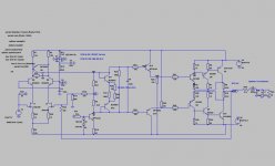
Attached find an interesting amp which I designed with LTSpice.
The design objectives were:
1.) the harmonics spectrum should stay constant ( that is the relations of the amplitudes of h2 to h3...h9, h3 to h4..h9 etc) in db independent of frequency from 20 hz to 6000 hz
2. the harmonics spectrum should be constant from 1% to 90 % of full power
3. the harmonics spectrum should be independent of reactive ( i.e. complex) load
This amp has little overall feedback. The thd is not at all low, in fact it is about 0.3% but objectives 1 to 3 are met. I have been testing with various speaker models, also 4 way with complicated crossover, and electrostatic midrange/tweeter. In simulation, it works.
The really built amp, tested with a spectrum analyzer , matches the Spice sim
closely but has in fact less thd about 0.15% . The sonic quality reminds vividly of good to very good tube / triode amps.
Hans Dieter
Attachments
Attached find an interesting amp which I designed with LTSpice.
The design objectives were:
1.) the harmonics spectrum should stay constant ( that is the relations of the amplitudes of h2 to h3...h9, h3 to h4..h9 etc) in db independent of frequency from 20 hz to 6000 hz
2. the harmonics spectrum should be constant from 1% to 90 % of full power
3. the harmonics spectrum should be independent of reactive ( i.e. complex) load
This amp has little overall feedback. The thd is not at all low, in fact it is about 0.3% but objectives 1 to 3 are met. I have been testing with various speaker models, also 4 way with complicated crossover, and electrostatic midrange/tweeter. In simulation, it works.
The really built amp, tested with a spectrum analyzer , matches the Spice sim
closely but has in fact less thd about 0.15% . The sonic quality reminds vividly of good to very good tube / triode amps.
Hans Dieter
The VAS stage looks like Lender's circuit
http://www.diyaudio.com/forums/soli...age-large-voltage-swings-lenders-circuit.html
What about R26/28? Why are this connect to the supply rails instead the output line?
In general there is no justify to make such complicated topology (my experience). My favorite design is that one from the links by post #13 about
http://www.diyaudio.com/forums/solid-state/99967-anybody-have-scan-483b-motorola-2.html
in an optimized version
If you have build both topologies in high quality standart you will not able to say, which of them is clearly better - for this I am quite sure.
A great disadvantage of your topology is the DC coupling of the speaker and therefore an relais contact in series to the speaker wire for DC protect.
Last edited:
Connecting R26/28 to output has negative influence on OLG as well as on open loop cutoff frequency and thus violates design objective.
Btw the insensitivity to reactive load comes at the expense of damping factor
which is independent of frequency but quite low about 100.
Also btw with a symmetric input the design objectives are not met. The 2N5196
has two jFET on one chip and hence low temperature drift and almost identical
charcteristics there is no pFET available with such properties.
The URL about Harmans T-Circuit: "An Ultra-Low Distortion Direct-Current Amplifier" from the authorIn the meantime I have find this:
QuadTriple, Harman's T-Circuit, Triple Cascade, Elektor's EQUIN
http://www.diyaudio.com/forums/solid-state/160285-class-b-w-o-crossover-distortion-1975-a.html
Harmans T-Circuit: "An Ultra-Low Distortion Direct-Current Amplifier" from the author
BART N. LOCANTHI (James B. Lansing Sound, Inc.)
http://www.harman.com/EN-US/OurComp...ip/Documents/Scientific Publications/1091.pdf
http://www.diyaudio.com/forums/solid-state/113943-quad-303-triple-cascade-3.html (post #21)
EQUA-Verstaerker HiFi Verstaerker bis 100W - 1972, december, page 1216
Von DIN zur EQUA-Norm Normen fuer HiFi Anlagen - 1972 december, page 1215
but actually there must be more - thank you for additional advices.
BART N. LOCANTHI (James B. Lansing Sound, Inc.)
www.harman.com/EN-US/OurCompany/Technologyleadership/Documents/Scientific Publications/1091.pdf
is death. Here the currently URL:
http://www.aes.org/tmpFiles/elib/20110325/1091.pdf
in this case this thread is also of interest:
http://www.diyaudio.com/forums/solid-state/188143-groner-triple.html
http://www.diyaudio.com/forums/solid-state/188143-groner-triple.html
The URL fom post #27 (Harmans T-Circuit) is death again. Here the currently URL:
http://www.aes.org/tmpFiles/elib/20120704/1091.pdf
http://www.aes.org/tmpFiles/elib/20120704/1091.pdf
Only truly experienced (and unfortunately very few) developers (like Quad) achieve a design of such triple stages without any oscillation under any load condition.
I recall, that I have for checking a diy amp device, that uses also such - slightly different topology:
The name was "Equa" from German magazine "Elektor" December 1972, page 1216
This amp was an unwanted oscillator (even by p-Spice simulation and in real life only to test by current limited power supply without destroy the output devices).
Only after remove one stage in the output buffers I get satisfy operating.
About this address perhaps there is a complete Equa schematic available:
Audioclub Oost Brabant, clubavonden
I want to have basic articles about such three stage super ß quasi complementary stages. Who knows more about this?
I know too few English keywords therefore. I recall, that I have read some years ago a JAES article. But I don't know if it was the main topic.
Check out follow replies to post #3403 about
http://www.diyaudio.com/forums/soli...erview-negative-feedback-341.html#post3188517
I have lost the original magazine, a UK edition but "Elektor" Summer Circuits edition 1980, had a 2N3055 "supertransitor" quasi circuit if I recall correctly. THD was quite low, bias 25-100mA. Perhaps this is of interest.
Recently, I bought a VGC Quad 303 and came across another commercial design in my searches, with the same output stage. If I can find it again, I'll post a link
Recently, I bought a VGC Quad 303 and came across another commercial design in my searches, with the same output stage. If I can find it again, I'll post a link
Last edited:
Yes; the attached file by post #2 aboutIan, FYI the Crimson Elektrik amps used this output stage. I think tiefbassuebertr already knows about them
http://www.diyaudio.com/forums/solid-state/134733-crimson-krimson-amp-schematics.html
show a schematic.
I have lost the original magazine, a UK edition but "Elektor" Summer Circuits edition 1980, had a 2N3055 "supertransitor" quasi circuit if I recall correctly. THD was quite low, bias 25-100mA. Perhaps this is of interest.
In the summer edition from German's magazine Elektor (1983) is in fact a beta enhancer, but with a quadruple (instead a triplett) arround a 2N3055. The actually wrong headline is follow: "2N3055 Darlingtons" (circuit number 73, page 7-92). For the positive half there is at first a NPN (BC546B), then a PNP darlington consist of a BC556B and a BD140 and then the 2N3055.
For the negative half there is at first a PNP (BC556B) and then a NPN triplett consist of a BC564B, BD139 and a 2N3055, but it seems to be a missprint, because the emitter of 2N3055 from the neg. half goes not to the negative rail.
The main issue for me by these methods of beta enhancing is the fact, that there are no clearly design rules.
Please note: by quasi complementary tripletts there are three different arrangements for the topology, and in case of a quadruple yet much more. Also by the idle current for each transistor stage there are very many possibilities.
Last edited:
by chance I read this statement concerning the output buffer stage of internal circuit of the LM3886 from TI (formerly NS) underare there any news concerning design rules for quasi complementary triplet cascades?
http://www.ti.com/lit/ds/symlink/lm3886.pdf
on page 7:
One common question is whether the output section of the amplifier is biased into Class-A operation. Technically, the answer is “yes,” as the exceptional linearity of the output section design achieves the advantages of pure Class-A operation.
Using the “Intelligent Power Transistor with Gain” system keeps the output section properly biased at all times to eliminate crossover distortion caused by the output transistors during turn-on and turn-off, as opposed to the brute force Class-A biasing techniques used in other inadequate amplifier designs to compensate for poor linearity that result in low efficiency, excessive heat, electrical waste, and the need for power management.
I note, that both driver and output stage at both halfs are create by a NPN darlington configuration - only at the neg. half there is a PNP transistor and two diodes for phase inverting (only small signal area). It seems to be an advantage, that no PNP high- and medium power transistor is in use inside of the output power buffer. Is my estimate right ? If yes, there are no justify of the use for PNP power devices in output stages of new audio power amp projects.
I would like to know, where this approach from LM3886 with only NPN transistors in the output buffer (maybe for the remove of residual class-B distortion) is realized in discrete power amplifiers - thank you very much for an advice.
Last edited:
One common question is whether the output section of the amplifier is biased into Class-A operation. Technically, the answer is “yes,” as the exceptional linearity of the output section design achieves the advantages of pure Class-A operation.
This is of course a pure lie - they say that the stage is as good as class A, not that it is biased in class A, which it is not. A lie.
As to your other questions: the use of NPN-only stems from the time that fast complementary PNP power devices were simply not available and they were 'fudged' with an NPN with a PNP driver.
That they now can turn this ancient, technically inferior method around and present it as something positive is a tribute to a very good marketing department and an advanced technique called lying .

Jan
I did not see this description on page 7!.
However, some comments on the Quad 303 triples: in evaluation circuits I have built, only the original RCA-2N3055 (the old slow hometaxial devices) did not oscillate. With the newer faster devices, I had to make some circuit changes to prevent oscillation. I have successfully tested two OP stages using BD139/BD140 pairs in the triples, and ZTX304/ZTX504 input followed by BD139/BD140 with the new 2N3055's, and doubled the frequency response over the original 303.
I have found that, I think along with many others, a straight triple NPN/NPN/NPN and complement are more stable than any combination of inverting triplets.
To set the quiescent current in the Quad, I usually monitor the VAS collector voltage. Since that exhibits greater distortion it is easier to see whether the response has a straight line in the crossover region, or is faster (too low a bias) or slower (too high a bias) - but with the RCA-2N3055(H) the optimal currents were different at 1kHz and 20kHz, so I set it for 20kHz. Not so obvious with the faster devices.
Regarding the 3886, it seems that the PNP's are probably lateral types with low gain. That would allow them to work at high differential input voltages (as they don't have "true" emitter-base junctions) and does not add a particularly high gain which would cause imbalance in the OPS. The kink in the distortion at around 1W looks strange, not something I have seen in the 303 output (have seen a more gradual kink) but the level of distortion may be low enough so as not to be audible.
Eliminating crossover distortion seems best addressed by avoiding Miller capacitors in the VAS stage. Instead, use passive C or CR loads (to ground) e.g. 47-220pF (depending to some extent how much current the VAS can supply) and global compensation or at least output inclusive Miller, but I have not seen the technique used in the 3886 used in a discrete design - probably no need!
Cherry suggested OIM stabilisation (but did not call it that) in his "nested" circuits, which seems to account for the low crossover distortion in his design, rather than the nested feedback, from what I have investigated.
Last edited:
please show us a screenshot! I know NS datasheets have degraded in language and intellectual requirements some years ago. Yet such a statement is not part of the actual datasheet and it was not in the late 90's when I build an amplifier with LM3886.by chance I read this statement concerning the output buffer stage of internal circuit of the LM3886 from TI (formerly NS) under
http://www.ti.com/lit/ds/symlink/lm3886.pdf
on page 7:
One common question is whether the output section of the amplifier is biased into Class-A operation. Technically, the answer is “yes,” as the exceptional linearity of the output section design achieves the advantages of pure Class-A operation.
Using the “Intelligent Power Transistor with Gain” system keeps the output section properly biased at all times to eliminate crossover distortion caused by the output transistors during turn-on and turn-off, as opposed to the brute force Class-A biasing techniques used in other inadequate amplifier designs to compensate for poor linearity that result in low efficiency, excessive heat, electrical waste, and the need for power management.
Last edited:
- Status
- This old topic is closed. If you want to reopen this topic, contact a moderator using the "Report Post" button.
- Home
- Amplifiers
- Solid State
- Quad 303 triple cascade