Hello
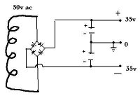
I did found a nice big 50 volt ac power transformer, but there is no center tap and it would be quite trouble to take it apart to do a center tap.
I know that we can do virtual center tap by using two big capacitor, like the drawing I've done.
But is it ok to use that virtual center tap for a power amp, is there any possible problems ?
Thank
Bye
Gaetan
Attachments
Quad thing looks strange to me. - Does that really work?
But you can definitely do this:
Solution 1)
-¤----------->|-------------- +70V
|
|
-------------------------------------- 0
|
|
--------------|<-------------- -70V
...gives you double voltage which might limit the use, and also gives you only half the rectified signals, as positive and negatives are split. This gives more ripple when you use heavy currents.
Solution 2)
Use it for a singlesupply poweramp, one with a capacitor in the output. It is not as bad as you would think.
By studying it closer I can now see, that for the speaker output the two capacitors act as the output capcaitor in a single supply amplifier.
Hmmm you are right it works, but the capacitors are in the signal path.
I would keep the T11/T12 arrangement, if I would ever copy this.
Hmmm you are right it works, but the capacitors are in the signal path.
I would keep the T11/T12 arrangement, if I would ever copy this.
hi,
take a closer look at the voltage divider provided for the rail caps
http://www.audio-circuit.dk/Schematics/Quad 306 Schematic.pdf
take a closer look at the voltage divider provided for the rail caps
http://www.audio-circuit.dk/Schematics/Quad 306 Schematic.pdf
Hi
I agree with Elwood. The PS quality is very important and the amp should be designed for IT. After all, you are listining to the power supply modulated by the audio signal. Whether it be a small, regulated higher voltage drive supply for the amplifying/driving circuits and a robust lower voltage supply for the outputs as in Mosfet follower amps, physical layout is important too, something hard to simulate 'exactly' on a PC.
I agree with Elwood. The PS quality is very important and the amp should be designed for IT. After all, you are listining to the power supply modulated by the audio signal. Whether it be a small, regulated higher voltage drive supply for the amplifying/driving circuits and a robust lower voltage supply for the outputs as in Mosfet follower amps, physical layout is important too, something hard to simulate 'exactly' on a PC.
Hi,
I've used Quad's idea for a couple of power supplies with untapped transformers, and it works fine. The amps were fairly standard class B designs, along the lines of Doug Self's amplifiers
You just need to add two transistors (T11 and 12) and four resistors (R28-31). I don't think that any of the values are critical. I used a BD139 and BD140 for the transistors because I had then lying around.
One thing you should note about the Quad power supply is that the positive and negative rails are slightly asymmetrical (about +39 and -41 V). You should be able to make them equal by making R28 & 29 both the same (10K or so).
The quad amplifier also uses an opamp (IC 1) to servo the output offset to zero, but I found that this was unnecessary, as the DC offset was less than 50mV anyway.
The majority of QSC amps are made this way, this model uses your exact transformer voltage:
http://www.qsc.com/support/library/schems/Discontinued/Series One/1080.pdf
http://www.qsc.com/support/library/schems/Discontinued/Series One/1080.pdf
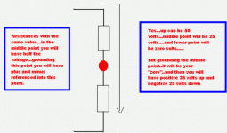
Will not work fine...you will need to produce current... huge current
crossing from minus to plus..... or the opposite if you prefer to understand this way...to allow the mid point voltage that you will call "zero".... then you will have positive voltage refered to that (up) and negative voltage referenced to that (low).
The problem is the waste of energy and you will have only a small part of that current to use..... if you try to suck current from this system the voltage will be extremelly reduced.
I have tried, several times, when was young.... i concluded do not worked those days.
Enormous electronic convertion will be needed...you will have to construct oscilators to positive and negative part...will be a switching supply using your transformer secondary... and to use a switching supply plugged into 2 wires AC system...we go directly to our wall outlet.
Sorry.... at least i cannot imagine how.
Maybe on of our friends have the solution.
I use to dismount the transformer, to rewind it with double wire.... the same number of turns...and them the result will be three wires...the starting piece extreme point will be twisted together and soldered... this will be the center tap.... the other extreme... 2 points extreme... 2 wires extreme points will be your AC voltage.... both referenced to the center (the common starting point)
regards,
Carlos
Attachments
The QSC power supplies are similar, but their amplifier circuits work a little differently than normal. They have grounded outputs (the collectors of the power transistors) and floating power supply rails. To make an amplifier like this you will need a separate supply for each channel, in addition to a separate +/- 15 V supply for the front end of the amp. I've never really understood the advantage of this configuration, except that it allows you to bolt the output transistors directly to the chassis without any insulation.
I should also mention the amps that I have made with the Quad-type power supply had a separate power supply for each channel (I used transformers with two 50 volt windings). I'm not sure that a single power supply would work properly supplying two channels.
Andy
I should also mention the amps that I have made with the Quad-type power supply had a separate power supply for each channel (I used transformers with two 50 volt windings). I'm not sure that a single power supply would work properly supplying two channels.
Andy
Carlos,
All I can say is the the power supplies do, in fact, work just fine!
The only source of power loss that I can imagine is what is used by the two small transistors in the extra circuit, and this would be insignificant compared to the power amplifier's consumption.
I only made this circuit because I had some untapped transformers lying around and did not want to spend $$$ on another transformer. If I had had a normal transformer, I would have made a conventional power supply.
Andy
Just an observation, but 90% of the time the transformer isn't supplying any power as it's output voltage is below that of the charged capacitors, so the diodes disconnect it.
The center tap ensures that both capacitors are returned to the same potential 100 times per second.
The transistors in the quad circuit perform a similar function by bleading charge from the side with highest voltage. This works well provided the load on both sides have a similar load, if not the zero point will drift and the transistors will not be able to correct it.
My though is this circuit should be fine provided the load on both sides are similar. But I agree probably best to have separate supplies for each channel.
- Status
- This old topic is closed. If you want to reopen this topic, contact a moderator using the "Report Post" button.
- Home
- Amplifiers
- Solid State
- Using virtual center tap for a power amp ?