Hello to all friends, I just bought an used Proton 520 amp for quite a cheap price.
It went with the volume not functional, due to the interrupted contact of the pin of the volume potentiometer connected to the ground. It seems a diffused problem for this little amp.
I repaired it dismounting the potentiometer and applying a small amount of silver-based varnish to the pin electrically interrupted (the one on the left, if you see the potentiometer from front), now I have 1,5 Ohm resistance between the center and the left pins with the knob all rotate to the left, that is good enough for a 50K potentiometer.
After some restyling (silver mica capacitors instead of ceramic, bipolar decoupling capacitor in the signal path, better resistors etc.) I'd like to change the mute circuit: it uses a fet in series with the signal used as an electronic switch... probably the worst solution.
I haven't enough electronic skill to realize it, but the idea should be to mantain all the original circuitation, and use the fet to drive a two-way relay. Probably the fet can't drive the relay directly, so I'd need someone's help to realize a simple interface to drive an adeguate transistor (e.g. the bd 13* series).
I tested that the fet is normally off, with a -15,6 v (referred to the gruond) applied to the gate; after 5-6-seconds the fet turns on, and the voltage at the gate goes to zero.
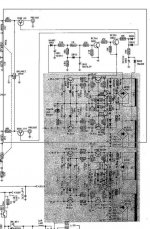
in attachement you'll find the schematics of the mute circuit, a big thank to all that will give me an help, and a great salute to all.
Max
It went with the volume not functional, due to the interrupted contact of the pin of the volume potentiometer connected to the ground. It seems a diffused problem for this little amp.
I repaired it dismounting the potentiometer and applying a small amount of silver-based varnish to the pin electrically interrupted (the one on the left, if you see the potentiometer from front), now I have 1,5 Ohm resistance between the center and the left pins with the knob all rotate to the left, that is good enough for a 50K potentiometer.
After some restyling (silver mica capacitors instead of ceramic, bipolar decoupling capacitor in the signal path, better resistors etc.) I'd like to change the mute circuit: it uses a fet in series with the signal used as an electronic switch... probably the worst solution.
I haven't enough electronic skill to realize it, but the idea should be to mantain all the original circuitation, and use the fet to drive a two-way relay. Probably the fet can't drive the relay directly, so I'd need someone's help to realize a simple interface to drive an adeguate transistor (e.g. the bd 13* series).
I tested that the fet is normally off, with a -15,6 v (referred to the gruond) applied to the gate; after 5-6-seconds the fet turns on, and the voltage at the gate goes to zero.
in attachement you'll find the schematics of the mute circuit, a big thank to all that will give me an help, and a great salute to all.
Max
Attachments
Ok... maybe was a too dull question, so I goes by myself, found a circuit at http://www.rason.org/Projects/transwit/transwit.htm and applied the circuit in figure 3 changing the 2N3906 with a BD136 and using the existing circuitation with the jfet used as electronic switch between R1 and ground.
I have taken the +V from the power line (the one that drive the output stage, not from the line supply) and putted an 820 ohm resistor between the +V and the +12V in figure 3.
Obviously I used a higher voltage relay (a 24v DC one), in this condition I measured about 20V between the coil terminals. This give me a total current consumption of about 40-45 mA, that I believe is low enough, considering that it came from the end stage power supply, the strongest one. I think that with a correct realy the resistor can be omitted and the consumption can be lowered as well, but this is what I had in my hands, so...
The sound is incredible for a such cheap amp, you can't pretend a perfect control in the bass region, but from the mid bass to the high region is very, very smooth and relaxed, while don't miss exact instruments position focusing and right details. From many years I found that the first big improvement while tweaking is to substitute every ceramic capacitor in the signal path (especially the local feedback ones) with silver mica one, probably due to the well-knowed issue of the piezoelectric effect that affects the ceramic ones.
At least, a modification that I can only strongly recommend to the Proton 520 owners.
CD player: East Sound CD E-5
cable: IBM CAT6 token ring in semi-balanced configuration
Speakers: Lowther DX3 in dipole arrangement
Don't ask to me which kind of cables I use for the speakers: it's simply a shame...
A big salute to all friends
Max
- Status
- This old topic is closed. If you want to reopen this topic, contact a moderator using the "Report Post" button.