Have replaced blown output transistors, placed 15R resistors across rail fuses as per service manual but the quiescent current is far too high.
Seems the culprit is still there...
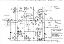
Anyone wanna take alook at the schematic and give me some pointers?
http://www.retrohifi.co.uk/a60_amp_service_manual.pdf
Cheers,
Steve.
Seems the culprit is still there...
Anyone wanna take alook at the schematic and give me some pointers?
http://www.retrohifi.co.uk/a60_amp_service_manual.pdf
Cheers,
Steve.
If the outputs blew it's likely that the driver transistors are damaged too. Check these - Q18/19 on left, Q118/119 on right.
You will need to adjust the quiescent current whenever you fit new transistors. This is done by adjusting RV2. Honestly, I don't like the way the bias circuit works on this amp, but thats how it works as stock!
If you're prepared to do a little tweaking, this page is full of useful goodies: http://myweb.tiscali.co.uk/nuukspot/decdun/a60mods.html
If it were my amp, I'd definitely do the mod of replacing R50 with the "amplified diode" (VBE multiplier).
Wow, you have a really old one!
See the schematic for the later versions. Arcam switched to the Zetex ZTX653/753 transistors. Looking at parts, BC639/640 may also be suitable, but the pinout is different.
I would replace with the Zetex transistors. You can get these from Rapid Online in the UK. Farnell also stock them.
See the schematic for the later versions. Arcam switched to the Zetex ZTX653/753 transistors. Looking at parts, BC639/640 may also be suitable, but the pinout is different.
I would replace with the Zetex transistors. You can get these from Rapid Online in the UK. Farnell also stock them.
Hah, SICOM NZ has them. Surprise of the year, just waiting for them to arrive.
I figure I might as well replace all of them as they are a lot cheaper than I thought they would be, will also do the A&R Cambridge upgrade from the service manual. Toying with the amplified diode mod idea... but it's not my amp, and my mate will probably just blow it up again in short order.
The rubber feet on the bottom are partially melted so I would say it gets a fair thrashing. Might have to scrounge a bigger heatsink from somewhere...
Cheers,
Steve.
Hi,
what is the DC voltage on each of the supply rails when you take these measurements?
Can your DMM measure AC voltage when also measuring across a high DC voltage?
I can set my DMM to 200.0mVac, when reading across 50Vdc and get an approximation of the ripple (average) on the DC rail.
what is the DC voltage on each of the supply rails when you take these measurements?
Can your DMM measure AC voltage when also measuring across a high DC voltage?
I can set my DMM to 200.0mVac, when reading across 50Vdc and get an approximation of the ripple (average) on the DC rail.
Appologies for the long silence, had to put this one on the back burner so to speak.
I guess I should have mentioned that this problem is in one channel only, the other has voltages pretty close to the figures in the service manual, and an acceptibly low quiescent current.
Anyway:
DC rail voltage is +-33.5v
I don't have a meter with a low voltage AC range, my gear is more suited to 100v+ / 50A+")
Output is at about 20mV on both channels, shorting r50 appears to have very little effect. Main caps seem ok.
Cheers,
Steve.
I guess I should have mentioned that this problem is in one channel only, the other has voltages pretty close to the figures in the service manual, and an acceptibly low quiescent current.
Anyway:
DC rail voltage is +-33.5v
I don't have a meter with a low voltage AC range, my gear is more suited to 100v+ / 50A+
Output is at about 20mV on both channels, shorting r50 appears to have very little effect. Main caps seem ok.
Cheers,
Steve.
Hi,
it still looks like there is a fault with Q18/Q19 - there is not enough Vbe voltage for these to conduct if they were working normally
Check the 2 current sources are working (Q11/12 and Q14/15 probably OK)
Also the voltage across R43
Also voltage to gnd at R50 ...
My guess is that Q13 is toast maybe taken your replacement Q18/19 with it
I can remember when a friend bought one of these new,
i was very jelous at the time
Q9,10,11,12 replaced (I had plenty of bc547s lying about).
Fire it up, everything seems normal, quiescent current bang on the book
20 seconds later back to square one :-(
I replaced Q13 at the same time as Q18/19
I assume this is a thermal issue as if I leave it off for a couple of minutes I get a repeat performance.
Cheers,
Steve.
Fire it up, everything seems normal, quiescent current bang on the book
20 seconds later back to square one :-(
I replaced Q13 at the same time as Q18/19
I assume this is a thermal issue as if I leave it off for a couple of minutes I get a repeat performance.
Cheers,
Steve.
Either a dry solder joint or a leaky electrolytic ?
Are any of the signal transistors getting noticably hot ?
At this age its probably worth replacing the 3 small electros on each channel anyway, they won't see much polarising voltage and may well be leaky by now. Still, i can't see how thay could cause the problem you are seeing
Are any of the signal transistors getting noticably hot ?
At this age its probably worth replacing the 3 small electros on each channel anyway, they won't see much polarising voltage and may well be leaky by now. Still, i can't see how thay could cause the problem you are seeing
- Status
- This old topic is closed. If you want to reopen this topic, contact a moderator using the "Report Post" button.
- Home
- Amplifiers
- Solid State
- A&R Cambridge A60 help