Wouldn't that be only when driven that hard? With a lower rail voltage wouldn't be closer to clipping and the nasty artifacts of all the protection circuitry reacting.
I have however never understood why the graph in the datasheet is interpreted the way it is although it may seem reasonable. I just think of it as the limits versus rail voltages for continuous use. When rails are lower you can supply maximum rail dependant power into lower loads. That however for me does not say much but maybe I am slow. I just see the higher rails as the possibility to supply the maximum power intermittently into higher loads and still pretty good. I will run my GCs with 35 V rails.
I would seek the solution elsewhere before lowering the rails. Bass shy would not be the result IMHO if you were limiting the way the graph suggests. Unacceptable sound would be.
PaulHilgeman said:Is this possible? How so? I think I have come to a conclusion on my lack of bass. I am running 35V rails on my gainclone, and my speaker dips down to about 4.5 ohms at 35 Hz, which could force the gainclone into not operating as it should in this reigon.
-Paul
Hi Paul,
the use of a series choke, resistor or thermistor between the bridge rectifier and the smoothing capacitors will lower the voltage a little and also decrease ripple. However, I don't think this will be enough in your case. You could unwind a few turns from the secondaries of the transformers. This is possible with a standard E-I transformer and may be possible in the case of toroids as well. Peter Daniel, I think, has mentioned this a few times and may be able to give practical details.
If you don't want to go to all this trouble then new transformers with lower secondary voltages ( 24-0-24 V seems to be recommended for gainclones ) may be a more convenient solution.
James
Re: Re: Lowering Supply voltage of a Toroid
Choke, resistor or thermistor would not be recommended for this amp as that would cause severe dynamic compression IMHO. Actually it seems he is running 24 V secondaries already. 18 V would be the key to safe graph areas giving some 23-24 VDC at load.
nemestra said:
Hi Paul,
the use of a series choke, resistor or thermistor between the bridge rectifier and the smoothing capacitors will lower the voltage a little and also decrease ripple. However, I don't think this will be enough in your case. You could unwind a few turns from the secondaries of the transformers. This is possible with a standard E-I transformer and may be possible in the case of toroids as well. Peter Daniel, I think, has mentioned this a few times and may be able to give practical details.
If you don't want to go to all this trouble then new transformers with lower secondary voltages ( 24-0-24 V seems to be recommended for gainclones ) may be a more convenient solution.
James
Choke, resistor or thermistor would not be recommended for this amp as that would cause severe dynamic compression IMHO. Actually it seems he is running 24 V secondaries already. 18 V would be the key to safe graph areas giving some 23-24 VDC at load.
UrSv said:
Choke, resistor or thermistor would not be recommended for this amp as that would cause severe dynamic compression IMHO.
If the filter capacitance was increased from the 1000 - 4700 uF range commonly used for gainclones up to a more 'normal' 10000 - 20000uF value then all of the above should work fine.
UrSv said:
Actually it seems he is running 24 V secondaries already. 18 V would be the key to safe graph areas giving some 23-24 VDC at load.
Agreed.
James
Dear UrSv
I don't know which chip you are using, but what i have seen in application notes of National and Thomson may hold true for all monolithic power ICs.
These ICs are tracking their power consumption and their Safe Operation Area by close monitoring the "junction temperature", that is point(s) inside the chip. Some are using global temperature and some point temperature tracking.
If the load is 4 Ohms, the internal power consumption rises high , so internal temp rises high very fast (at a rate that does not reflect to the temp of the heatsink), so internal temp. monitoring activates safety mechanisms, which in most cases are either cliping the peaks or are lowering the drive of output devices. This may form a mechanism of reduced bass at high levels with 4 Ohms (low frq has longer period, thus more time for activation). The chip manufacturers claim the onset of safety mechanisms activation at much lower power output than the nominal specified(approx at 1/2-2/3 depending on the signal form).
So for 4 Ohm load, they recomend lower supply voltage (+/_28V Volts, against +/_ 37V for 8 Ohm) if maximum output is to be acheived.
Regards
George
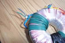
If you wish to lower voltage of your secondaries, here's an easy tip.
Add a winding connected in serie with your secondary.
This way, you can increase or decrease voltage simply by changing the number of winding around your toroid.
Do this twice... once for each of your secondaries
If you want to increase voltage, connect your winding on one the the secondary wire and vice-versa if you wish to lower voltage.
Hope this helps !
Attachments
PaulHilgeman said:Is this possible? How so? I think I have come to a conclusion on my lack of bass. I am running 35V rails on my gainclone, and my speaker dips down to about 4.5 ohms at 35 Hz, which could force the gainclone into not operating as it should in this reigon.
Paul, can you give any explaination of how your idea has accured? What things control the bass reproduction?

I tried my gainclone with 2 identical transformers (Plitron 400VA,) the only difference was secondary voltage. First one had 24-0-24V, the other was 18-0-18V, which I acheved by removing secondary windings. The amp connected to lower voltage supply, was clearly producing more bass into same load.
-----------------------------------------------------------Peter Daniel said:I tried my gainclone with 2 identical transformers (Plitron 400VA,) the only difference was secondary voltage. First one had 24-0-24V, the other was 18-0-18V, which I acheved by removing secondary windings. The amp connected to lower voltage supply, was clearly producing more bass into same load.
Sorry for the ignorance; what is the Gainclone?
Can the bass change be related to power transformer impedance, not necessarily voltage. Id the dc supply regulated after the ac?
What might be the best way to achieve this be? Wind a wire in the opposite direction of the secondary winding, or actually take wire out? It seems that I get about .5V per turn that I add when adding a loose wire.
I guess it depends if you care or not to permanently lower your voltage by removing some winding on your transformer.
In my case, I prefer to keep the original 30-0-30V secondaries just in case
)It is normal to get around 0.3-0.5V per turn depending on the transformer.
Regards
- Status
- This old topic is closed. If you want to reopen this topic, contact a moderator using the "Report Post" button.
- Home
- Amplifiers
- Solid State
- Lowering Supply voltage of a Toroid