Faust3D said:Can you recommend good current production low power (2-3 watts) MOSFET or JFET transistors with tube like characteristics? I am looking for good transistors that would be used in a hybrid headphone amp.
Thanks in advance.
I used both IRFP150 as well as 2SK1058 with SE valve hybrid. Worked well and sounded good.
Regards
Nico
Faust3D said:Thank you for the info.
Sorry mate, I don't know what happened with the last post, the values got left off. Here it is again.
Kindest regards
Nico
Attachments
Nico Ras said:
Sorry mate, I don't know what happened with the last post, the values got left off. Here it is again.
Kindest regards
Nico
Oops there is a mistake somewhere. Ignore this let me check my archives.
Nico
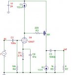
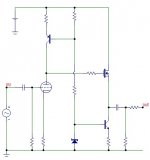
You should change many things on this circuit:
a) The tube does not need an input coupling cap.
b) If you put the coupling cap on the input of the MOSFET instead of the output, you can get away with a value around 0.22 uF (polystyrene is best, polypropylene is OK). This will sound much better than any electrolytic you put at the output.
c) You show a 1.5 amp CCS. This is huge overkill and will place great demands on everything. Assuming the MOSFET is biased halfway between the rails, it will be dissipating 18 watts. This will require a large transistor (100 watts or more) mounted on a very large heatsink.
Go back to the drawing board and try again. It will help if you know the impedance and sensitivity of the headphones you will be using. In any case, I can't imagine that you will need more than 1 watt of class A power. I also can't imagine that you will need more than +/- 6 volts of rails (12 volts total). I'd say 250 mA of idle current will be way more than enough. That will put you in class A up to 1 watt with 8 ohm headphones. If you have 300 ohm headphones, that is enough current to give 35 watts of class A (if the rails would swing that much, which they won't).
Charles Hansen said:I'd say 250 mA of idle current will be way more than enough. That will put you in class A up to 1 watt with 8 ohm headphones. If you have 300 ohm headphones, that is enough current to give 35 watts of class A (if the rails would swing that much, which they won't).
1W rms?
35W rms?

Charles Hansen said:You should change many things on this circuit:
Not to mention the amazing gain.
Not to mention:
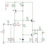
- 12AX7 bein perhaps the most unsuitable tube to work from a 24V power supply, for a number of reasons - one of which is high Rp and very low usable current at such low voltage, too low even to drive a relatively small IRF610. Also, at such a low current biasing inevitably goes into a very nonlinear part of the characteristic even with a CCS load, which seriously limits the usable voltage swing (refer to real curves for the 12AX7, not the simulator model which is FAR too optimistic!). Because of this the DC operating point of the MOSFET has to be shifted up towards the power rail, which decreases the Vgd of the MOSFET into a reguion where it's input capacitance is very nonlinear and quite a bit larger than one would expect even in a follower configuration. The Vgs treshold also further reduces the output voltage swing - optimistically it would be perhaps 10Vpp.
- 12AX7 has way too much gain (~100). With the input being from a CD player, a gain of 10 would already be too high. Even a 12AU7 would be more suitable, and more linear under the circumstances, although it would work much better with about 0.5mA of plate current, biassed at -0.35V or so, with about 16V on the plate. The nonlinearity problem of the input capacitance of the MOSFET however reamins for any larger swing, in some form, regardless of which tube is used. Of course, 6DJ8 or ECC86 would probably be even more suitable, particulairly the latter being made for operation at low plate voltages.
- In order to maximize available swing, the current sources need to drop as little voltage as possible. Current mirror types would probably work best here.
- You cannot simply use a coupling cap in front of the MOSFET to eliminate the output cap in this configuration, regardless of what Charles Hansen says. In order to do that, you would need a dual power supply (+-) and a temperature compensated MOSFET biasing network to avoid excessive DC offset on the output, in addition to the coupling cap. This would, however, have numerous other advantages, one of which would be largely avoiding the issue of nonlinear input capacitance of the MOSFET. The limited output swing would, unfortunately, remain.
- 1.5A standing current for the MOSFET would indeed somewhat linearize it (if the MOSFET is sufficiently small and this current is about 10-50% of the maximum, depending on MOSFET technology used so that this operating point falls into the flattened region of the transconductance vs drain current region), but t he heat produced and power required is prohibitive. Theoretically just 160mA would be enough for even 32 ohm headphones, so 250-300mA proposed adds a healthy margin. !A would be more than enough for 8 ohms - perhaps even lower given the mimited swing.
- be sure to use an appropriate output capacitor so it does not make a high-pass filter at a too high frequency with the impedance of the headphones. For 32 ohms, you need about 710uF, rounding up to the first standard value gets you to 820 or 1000uF! For 8 ohms you need 4x that amount (all based on 7Hz F-3, which gives about 0.15dB drop at 20Hz).
- Like Charles hansen said, you don't really need a coupling capacitor on the input. For some tubes there may be an issue of grid current in which case a coupling cap may be necessary, though.
of course, the best advice i could give is that you really need more voltage for the tube, and/or a different tube, and start from there.
Faust3D said:Great info guys, but what I am really looking for is model numbers of great JFETs and MOSFETs.
JFETs will be out of the question here. There used to be some that you could have used, had you been around about 30 years ago.
Regarding MOSFETs, their potential for greatness will never be achieved, not even remotely, in this, anything but great, circuit. You can just as well use the bog standard IRF510 or 610, which actually are pretty good.
This is kind of like asking a question of what alloy wheels to use on a wheelbarrow.
ilimzn said:JFETs will be out of the question here.
As if a 2SK60 would hack it, besides bing a darn shame to use.
Charles Hansen said:You should change many things on this circuit:
a) The tube does not need an input coupling cap.
b) If you put the coupling cap on the input of the MOSFET instead of the output, you can get away with a value around 0.22 uF (polystyrene is best, polypropylene is OK). This will sound much better than any electrolytic you put at the output.
c) You show a 1.5 amp CCS. This is huge overkill and will place great demands on everything. Assuming the MOSFET is biased halfway between the rails, it will be dissipating 18 watts. This will require a large transistor (100 watts or more) mounted on a very large heatsink.
Go back to the drawing board and try again. It will help if you know the impedance and sensitivity of the headphones you will be using. In any case, I can't imagine that you will need more than 1 watt of class A power. I also can't imagine that you will need more than +/- 6 volts of rails (12 volts total). I'd say 250 mA of idle current will be way more than enough. That will put you in class A up to 1 watt with 8 ohm headphones. If you have 300 ohm headphones, that is enough current to give 35 watts of class A (if the rails would swing that much, which they won't).
Hi Charles,
fistly, I spent about a total of one hour on this design using what I have. It drives speakers not headphones. It sounded okay and I offered it as a kick off point for some ideas and not as a high end DIY amplifier.
Kind regards
Nico
jacco vermeulen said:
As if a 2SK60 would hack it, besides bing a darn shame to use.
Darn shame is right, but even then you would have a problem biasing it, Vp is something like 16V if i remember correctly, and the relatively low gm would gobble up the already way too small voltage swing from the triode.
This design (appropriately corrected) really needs the almost impossible: a linear, high gm, low treshold, low input capacitance MOSFET. Very tall order. Perhaps some of the low treshold low votage types designed for very high speed switching (low gate charge) devices would work...
- Status
- This old topic is closed. If you want to reopen this topic, contact a moderator using the "Report Post" button.
- Home
- Amplifiers
- Solid State
- MOSFET or JFET