Hi all,
I'd like to make a (pair of) Crescendo Millenium Edition. However I had some problems with fake components in the past.
So I want to have real components in this time. Do you know any good supplier sells,
2SK1530 (Matched)
2SJ201 (Matched)
2SK537 (Matched)
MJE340
MJE350
OP77
Anda another question; May you say something about the Crescendo? Is it worth to make?
Thx..
Dxvideo said:Hi all,
I'd like to make a (pair of) Crescendo Millenium Edition. However I had some problems with fake components in the past.
So I want to have real components in this time. Do you know any good supplier sells,
2SK1530 (Matched)
2SJ201 (Matched)
2SK537 (Matched)
MJE340
MJE350
OP77
Anda another question; May you say something about the Crescendo? Is it worth to make?
Thx..
Hi Ozgur,
looks like you cannot make up your mind what you want to build. Well here is something else that you can build from your scrap box. I know you have everything you need for this baby and you can easily buld it on proto-board.
This is the classic John Lindsey Hood class A amplifier with a little twist. Instead of BJT I used MOSFETs. Simpler is hard to find and it really has a nice sound. It comes very close to the headphone sound you are looking for.
I think your Wharfdales are pretty efficient and will sound nice with it.
Kind regards
Nico
Attachments
Re: Re: Crescendo ME (component) question..
Hi AKSA,
The Crescendo which I want to make is the new version.. I choose it because its a complete design, with DC servo and all protections. But of course; the result is more important.
So you say, its sound is not as good as they told
Thx.
Dear Nico,
Youre right (as usual).. I am still confused. And still have no decision about the power amplifier.
I have a lot of project in my computer. Most of your projects. In fact its too hard to make a decision. Yes its too easy to make a prototype one. But as you know, last months I have a "time problem". So I want to make a final amplifier, which I can use in my living room.
Do you think this amplifier is too simple to give a good result? May be you find that question too stupid. But when I test a simple amplifier then I always disapointed.
Just a question...
Thx.
AKSA said:DXvideo,
It's an old design, not wonderful sounding, I made one in the eighties and modern designs sound better.
If I were you I'd build the Roender design in this forum, or even the Widowmaker design from Bulgaria. Both are truly visionary in my view.
Cheers,
Hugh
Hi AKSA,
The Crescendo which I want to make is the new version.. I choose it because its a complete design, with DC servo and all protections. But of course; the result is more important.
So you say, its sound is not as good as they told
Thx.
Nico Ras said:
Hi Ozgur,
looks like you cannot make up your mind what you want to build. Well here is something else that you can build from your scrap box. I know you have everything you need for this baby and you can easily buld it on proto-board.
This is the classic John Lindsey Hood class A amplifier with a little twist. Instead of BJT I used MOSFETs. Simpler is hard to find and it really has a nice sound. It comes very close to the headphone sound you are looking for.
I think your Wharfdales are pretty efficient and will sound nice with it.
Kind regards
Nico
Dear Nico,
Youre right (as usual).. I am still confused. And still have no decision about the power amplifier.
I have a lot of project in my computer. Most of your projects. In fact its too hard to make a decision. Yes its too easy to make a prototype one. But as you know, last months I have a "time problem". So I want to make a final amplifier, which I can use in my living room.
Do you think this amplifier is too simple to give a good result? May be you find that question too stupid. But when I test a simple amplifier then I always disapointed.
Just a question...
Thx.
Re: Re: Re: Crescendo ME (component) question..
Dear Ozgur,
What I have learned from you over the past year that we have been friends, (yes believe it one year) that you are a very critical listener and you are not satisfied easily.
Also you have created a problem by your listening to good headphones with class A, that is impossible to beat with anything other than better headphones and better class A. The most important is that you do not wake the new baby
My suggestion to you is and this is my honest suggestion, build DoZ from Rod's pages It cost very little. Then listen to it intensly. You will realise two things, firstly class A sounds very nice and secondly you do not need 100 watts.
Kindest regards my friend
Nico
Dxvideo said:
Hi AKSA,
The Crescendo which I want to make is the new version.. I choose it because its a complete design, with DC servo and all protections. But of course; the result is more important.
So you say, its sound is not as good as they told
Thx.
Dear Nico,
Youre right (as usual).. I am still confused. And still have no decision about the power amplifier.
I have a lot of project in my computer. Most of your projects. In fact its too hard to make a decision. Yes its too easy to make a prototype one. But as you know, last months I have a "time problem". So I want to make a final amplifier, which I can use in my living room.
Do you think this amplifier is too simple to give a good result? May be you find that question too stupid. But when I test a simple amplifier then I always disapointed.
Just a question...
Thx.
Dear Ozgur,
What I have learned from you over the past year that we have been friends, (yes believe it one year) that you are a very critical listener and you are not satisfied easily.
Also you have created a problem by your listening to good headphones with class A, that is impossible to beat with anything other than better headphones and better class A. The most important is that you do not wake the new baby
My suggestion to you is and this is my honest suggestion, build DoZ from Rod's pages It cost very little. Then listen to it intensly. You will realise two things, firstly class A sounds very nice and secondly you do not need 100 watts.
Kindest regards my friend
Nico
Dear Nico,
One year..... I feel we met just two months ago! Thats interesting. And another interesting thing is; you know my everything, as none of my colleauges knows.
Thanks for the advice.. I am sure it has a perfect and transparent sound. But by the time, my amplifier understanding has changed a lot. But I gues its not a HEALTY changing. Because the simple designs doesnt look like me good sounding... But I will try that, because of your advicing.
As I remember its a 8-10W (into 8 ohm) amplifier, I guess it will be enough for a 91dB 6ohm speaker. I have two 24v 4,5A SPMS module, so that means I can make two seperated amplifiers to put behind of my speakers.
I hope I will make that soon. I will be Austria again next week, then I can start a project.
Until the next time, take care of you..
Dear Nico,
Am I making a mistake or this amp has a 180° phase error on 1Khz???
Am I making a mistake or this amp has a 180° phase error on 1Khz???
An externally hosted image should be here but it was not working when we last tested it.
Dxvideo said:Dear Nico,
Am I making a mistake or this amp has a 180° phase error on 1Khz???
No, it's just that most simulators 'fold over' the phase shift at 180 deg, because they work under the assumption that +180 deg = -180deg (which would be true if we were operating along a circle, using regular trigonometry definitions). However, in electronics phase also implies delay, so unlike trigonometry, where A degrees + (N * 360 degrees) = A degrees, regardless of any whole N, in electronics things like 760 degrees phase shift make a lot of sense. Unfortunately, simulators use the trignometric definition when displaying the graph, which tends to give breaks like in your diagram, when there is polarity inversion. You can get the real situation by simply attaching the top part of the curve to the bottom part (shift it down to align), or use a mathematical function to display the graph, or in form of a circuit element to get the required polarity inversion.
Your diagram simply shows you that midband (1kHz) where the amplifier has minimum phase shift, the amplifier actually inverts polarity, which the simulator interprets as a 180 deg phase shift. Nothing to worry about - just reverse the speaker leads, if you want to keep absolute polarity (also referred to as absolute phase sometimes).
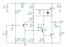
This is my circuit;
I had to make some mods on Nico version.
In fact its a mixture of Nico's and Rod's Project 83.. But I use MOSFET as CCS, and as I tested; to have 2A2 bias current the zener must be 6V2 not 3V0! Am I right?
Hey Nico; may you say something on it?
An externally hosted image should be here but it was not working when we last tested it.
I had to make some mods on Nico version.
In fact its a mixture of Nico's and Rod's Project 83.. But I use MOSFET as CCS, and as I tested; to have 2A2 bias current the zener must be 6V2 not 3V0! Am I right?
Hey Nico; may you say something on it?
Dxvideo said:Hmmm...
But if you take consider, after breaking point on the graph, there are a lot of phase shifts; for example it starts with 180° (on break point) but downs to 100° @ 1Mhz. That means phase response is not linear?
Of course it's not linear - amplitude drop-off implies phase shift, because it happens due to reactive elements, both intentional and parasitic. Every time constant you have in your circuit introduces phase shift at some frequency, it is the nature of filters. And, in your circuit there are at least 10.
At best, if your amp is completely DC coupled, and battery operated, you can make the phase shift at low frequency negligible.
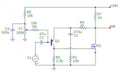
Dxvideo said:This is my circuit... I had to make some mods on Nico version... I use MOSFET as CCS, and as I tested; to have 2A2 bias current the zener must be 6V2 not 3V0! Am I right?
Yes, this should be correct, the required Vgs for the IRF540 at 2.2A is about 4V, which together with 2.2V on the 1 ohm resistor, gives a 6.2V zener. However, there is no particular need to pass a high current through the zener because there is negligible current through the MOSFET gate, so you can probably safely increase the 2.2k/2W resistor. The current that the gate sees is mostly due to the capacitance Cdg, you may want to put a small cap across the zener, and definitely you need gate stoppers on the MOSFETs - resistors in series with the gate terminal as close as possible to the MOSFET, about 100 ohm should do the trick. Without them MOSFETs tend to self-oscilate at tens of MHz...
ilimzn said:
Yes, this should be correct, the required Vgs for the IRF540 at 2.2A is about 4V, which together with 2.2V on the 1 ohm resistor, gives a 6.2V zener. However, there is no particular need to pass a high current through the zener because there is negligible current through the MOSFET gate, so you can probably safely increase the 2.2k/2W resistor. The current that the gate sees is mostly due to the capacitance Cdg, you may want to put a small cap across the zener, and definitely you need gate stoppers on the MOSFETs - resistors in series with the gate terminal as close as possible to the MOSFET, about 100 ohm should do the trick. Without them MOSFETs tend to self-oscilate at tens of MHz...
Very nice explanation Ilimzn.
Really good explanation...
And naturally, the next question is coming;
- Some diyers say; "LED is better than Zener" in CCS circuits. So if I want to modify CCS with zener, what circuit should I use? May you give a little drawing?
- If we take consider that is a single end design; should I feed it with a regulated supply?
Finally, a request, can anybody make a FFT analyse and give the THD results to me pls? I want to make that by myself however I have a 5spice analysis software and its demo version doesnt enable to analyse me that values.
Dxvideo said:And naturally, the next question is coming;
- Some diyers say; "LED is better than Zener" in CCS circuits. So if I want to modify CCS with zener, what circuit should I use? May you give a little drawing?
- If we take consider that is a single end design; should I feed it with a regulated supply?
For a LED CCS reference, you basically replace the zener with the appropriate number of series connected LEDs, and you calculate the series resistor to give you a sensible LED current, say between 2 and 10mA (higher being somewhat better because it lowers the impedance of the LED). Normally, you also can adjust the CCS current by manipulating the source resistor, but in this case I would not do so as the source resistor largely reduces the MOSFETs treshold voltage thermal coefficient.
LEDs have a somewhat higher impedance compared to zeners but for this sort of voltage they produce a LOT less noise. That being said, this is not an imperative in this circuit. You could, for instance, use two white LEDs in series, they each have a voltage drop of about 3V at 5mA. The only thing is that they are in general high efficiency types and at 10mA or so they will glow VERY brightly.
Regarding a regulated supply, it would be highly prudent to do so as the PSRR from the power rail is practically zero. All the noise from there gets transfered into the output.
This is because the input BJT is a very very good current source, and it's current is determined by the input voltage. The output voltage of this amplifying stage is actually the voltage drop on the collector resistor, i.e. colelctor current times the resistance. This means that the reference point for this voltage is actually the power rail, and not the ground rail - the voltage on the collector itself is equal to the voltage of the power rail, minus the amplified input - hence any change in the power rail gets directly superimposed onto the amplified input. because the power stage is a follower, this gets transferred tot he output practically unchanged.
It follows that the input stage at least has to have it's power rail filtered, if not regulated. Regulating the whole supply will give a very small added improvement compared to regulating/filtering the supply of the input stage. The simplest way to do this is to add a small resistor in series with the collector resistor, and connect the joining point of the two to ground via a large enough filter capacitor. This will, incidentally, also signifficantly reduce the 'pop' transient in the loudspeaker at power up. A zener could also be used instead, with carefully selected voltage, but this will not reduce the pop transient.
If this is done, the input biasing network can also be simplified because the added filtering is not needed any more.
- Status
- This old topic is closed. If you want to reopen this topic, contact a moderator using the "Report Post" button.
- Home
- Amplifiers
- Solid State
- Crescendo ME (component) question..