Agree guys perhaps the better thing to do is to listen to the real thing to find out if the clone will sound nearer to it. I have tested both channels in the same speaker while setting the bias current, they seem to sound pretty close to me but not an audiophiler here though, so could'nt tell accurately.
BTW has anyone tried 2SD1563/B1086 pair from Inchange Semis? from the specs they could qualify as better substitutes for VAS, they come in TO126 package.
BTW has anyone tried 2SD1563/B1086 pair from Inchange Semis? from the specs they could qualify as better substitutes for VAS, they come in TO126 package.
Member
Joined 2009
Paid Member
Agreed. There are are some semis that can be substituted without a great deal of impact but unless you can find very similar heavyweight transistors of around 30pF Cob for the VAS, you won't quite be hearing what you could say was "PRT". That's the Pace, Rhythm, Timing thing that was associated with Naim sound quality and marketing. Using this type of large die semi runs quite contrary to "state of the art" engineering principles but this is Naim, not SOTA.
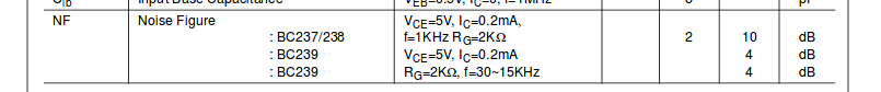
2SD1563 and 2SB1086 at 20pF and 30pF respectively, are much higher than normal output capacitance but you will probably find that originals ZTX types are still better as the Hfe range of these generic types (from a Chinese "Savant IC" generic datasheet) is not necessarily for the Hfe range you need. I guess if the Inchange parts are much cheaper than the Diodes Inc. ZTX parts, it may be worth an experiment but you still need to make a comparison between the types to know that what you have is optimal or at least close.
BTW, Element 14 sell ZTX 653/753 for Php 65.6 each, minimum qty5.
The ZTX753 has a 100V Vce rating, 140MHz typical ft and 1W power dissipation at 25C. The Zetecs are quite robust and fast. In a NAP with +-40V supplies and, say, 10mA Ic in the VAS, the transistor will dissipate about 400mW at idle and peak near twice that in normal operation. Junction temp. may be 70C higher than the surrounding air. At 400mW the transistor can cope with up to 120C air temperature, which is pretty hot, and about 40C at 800mW.
The feedback system obviously can't mitigate component characteristics in its sensing path. The dc blocking cap is in this path. Naim uses solid tantalums for both caps and they need to be high voltage to stop them breaking down under reverse bias. The higher the V rating of a tantalum the more reverse bias it can tolerate. A bipolar electrolytic can be used instead provided its HF response is good.I would stick with the original device types. But be careful with the input and feedback capacitors as they are both effectively outside of the feedback loop and so their sonic signature has more impact than some of the other caps.
Tantalums are relatively fragile. I recommend using bipolar electrolytics at least when experimenting because even a temporary large dc offset can damage a tantalum's dielectric or even destroy it. I caused a tantalum to shoot to the ceiling in flames once. That was fun.

Measuring/calculating phase margin of NCC200/Nap250
I built an NCC200 quite a few years ago and am very happy with it. I'm now curious to know what its phase margin is given that it was loosely based on the NAP250 which apparently had marginal stability.
I plan to run some simulations to explore the phase margin of the NCC , and perhaps the NAP250 as well.
There are a few methods which can be used, but they all involve placing some dummy elements into the negative feedback loop to break it completely. I seem to remember reading that the best place in the is where the output impedance of these dummy elements (a voltage and current source) is at a minimum?? in the feedback loop.
I'm just wondering where in the NCC and NAP250 circuits would be the best spot to place these dummy elements.
Would welcome any thoughts or suggestions.
You don't care about phase margin. Measure the thing you care about.I built an NCC200 quite a few years ago and am very happy with it. I'm now curious to know what its phase margin is given that it was loosely based on the NAP250 which apparently had marginal stability.
I plan to run some simulations to explore the phase margin of the NCC , and perhaps the NAP250 as well.
There are a few methods which can be used, but they all involve placing some dummy elements into the negative feedback loop to break it completely. I seem to remember reading that the best place in the is where the output impedance of these dummy elements (a voltage and current source) is at a minimum?? in the feedback loop.
I'm just wondering where in the NCC and NAP250 circuits would be the best spot to place these dummy elements.
Would welcome any thoughts or suggestions.
")
For example.
Phase margin doesn't tell you everything about stability except in a simplified, idealised, undergraduate electronics textbook where the circuit has defined poles and zeros and is perfectly linear and input and load invariant. That's not what real amplifiers are.
Better to observe the step response of the circuit.
The concern is about a Naim clone losing the plot with some loads. Try a range of capacitors but apply some means to current limit your amp in case it goes bananas. The older Naims could get upset when used with high capacitance speaker cable, I have read, which led Naim to specify using at least 3m(?) of Naim cable.
I built an NCC200 quite a few years ago and am very happy with it. I'm now curious to know what its phase margin is given that it was loosely based on the NAP250 which apparently had marginal stability.
I plan to run some simulations to explore the phase margin of the NCC , and perhaps the NAP250 as well.
I couldn't find the original Naim schematic in my LTspice projects but my Naim clone shows gm/pm of 19/83. So nothing wrong with phase margin but gain margin is slightly below my minimum standard which is 20dB. This proves that you are right with the tendency for instability because with other topology i have never get that low with gm.
These are great amp circuits, I have several. I used one as a guitar power amp as well as hifi amps. I would like to know what power supplies people have used to run them. For example, what transformer types and ratings and what caps and ratings.I have used 2x35v secondary's having 680VA total output into 3x10,000uf per rail.
The original spec. power supply for NAP 140 is +/- 34VDC. Larger models are maximum +/-40VDC and a regulated +/-40VDC is used for the NAP250 model. Supplier suggestions for Ebay kits are also +/-40VDC but you can take their model numbers and specs with a grain of salt, as their endless part substitutions and omissions mean you have very different amplifiers to the original, none of which will have much more than basic topology in common between them either. There is also an issue with transformers in that 28VAC windings are necessary for 40VDC but off-the-shelf transformers only come in 24(a few sizes),25,30 or 35VAC so you are either restricted to a NAP140 rating or frying the genuine components.
If you are referring to Avondale NCC200, this variation is modelled generally along NAP180 lines but is intended to improve on Naim sound quality - though at many times the low cost of Ebay clones.
The amplifier's supply voltage is restricted by the particular transistor types used for the VAS. In the NCC200 variation and all NAP models from the Chrome bumper series on, these are a particular Diodes Inc. complementary transistor pair, ZTX653/753, rated 80V Vceo max. which is why you can't mess with higher power supplies without wrecking the particular sound quality.
If your utility amplifiers have higher rated transistor substitutes, you can use somewhat higher supplies up to perhaps 50V with multiple output pairs as long as the bias current in the input and VA stages is then corrected to maintain the same operating points.
I guess you can do almost anything you like with amplifier circuits including fitting a second pair of output transistors, if they remain stable but of course, that's also another design with a new set of parameters.
I've found a simple supply is ok. Transformer (200VA+ say) with dual secondaries, each to its own full-wave bridge rectifier. A couple of 63V+ 10mF caps is fine with star ground between them like Naim does. Hint: the heavier the caps the better they tend to be.I would like to know what power supplies people have used to run them.
Regulators are a bit of a minefield for the non-expert and can cause more problems than they fix. I don't think they are necessary to get good sound quality; a perfect supply will not make a mediocre sounding Naim clone suddenly sound like a real Naim.
Last edited:
Quite so - 'seems I read the ZTX652/752 figures in haste.Ztx753/653 Vceo max 100V.......
I did try to use simulation to find out the phase and gain margins of the ncc200 using several methods but found the results to be inconsistent and meaningless.
Nevertheless I have been curious about the ncc200 and nap140 stability for some time because of several setbacks. In one case, 6 years ago, when I first started building amps I had a catastrophic failure through oscillation- caused by me because of very careless wiring.
I have heard that an ac analysis is only rough indicator of pm/gm margin but so far that's the best I have been able to achieve.
So I thought I would post a few of these: ncc200, nap140, elliott p3a just for general information.
Attachments
I have heard that an ac analysis is only rough indicator of pm/gm margin but so far that's the best I have been able to achieve.
From your attachment (picture for NAP140), PM/GM is approximately 80/17! My clone was 83/19. I am surprised with the low GM but that must be the truth about the topology (I don't design for PM/GM numbers, I just accept whatever they are as 'side effect' of my design objective or philosophy with a given topology)
- Home
- Amplifiers
- Solid State
- NAP-140 Clone Amp Kit on eBay