Yes indeed, same with all NAP clones built as per the original models. Note that this is not an instantaneous adjustment. The current will certainly change when you adjust the control but as the amplifier temperature then changes accordingly, it will slowly drift and settle to the new current. Before powering up, set the controls fully anticlockwise so that current is not set to maximum with the output transistors overheating. The process can take ages until you realise what goes on when you set bias current. To be more accurate and save time, lay the case cover in position with the meter leads still attached and after briefly raising the cover for each adjustment, continue to monitor the current as it stabilises to the new setting. Don't forget to read other reference(s) to Naim bias current setting method as per my earlier post and already detailed many times in this thread.
Also note that the Vbe multiplier transistors (next to the pots.) should actually be mounted on the bottom (copper side) of the PCB. This allows them to be close to the bottom plate which is also the heat sink and can give much faster settling. This is shown in pics and instructions attached to other seller's offers over the last year or so. Look around on the sites offering the CAOWEI boards.
Also note that the Vbe multiplier transistors (next to the pots.) should actually be mounted on the bottom (copper side) of the PCB. This allows them to be close to the bottom plate which is also the heat sink and can give much faster settling. This is shown in pics and instructions attached to other seller's offers over the last year or so. Look around on the sites offering the CAOWEI boards.
Anyone else feel like the NAP200 sounds a bit bass anemic? I don't know if it's my room or setup, but it sounds bass light.
**Add
also a big shout out to Ian Finch, thank you very much for being one of the biggest help in this thread if not the whole section. He kept repeating the same thing over and over again and linking the http://www.acoustica.org.uk/t/naim/power_amps.html for information. At first I didn't quite understand what the page meant but I scrolled down and found the Minor Mods/Servicing section and it all just clicked and made sense. (Almost) everything is already in there; suggestions, measurements, general circuit layout, parts name, Adjusting the output DC offset, Adjusting the bias (standing current), TR11 & TR12 OUTPUT TRANSISTORS, TR1 & TR2 INPUT PAIR etc.
I am truly humbled.
Last edited:
Good that you found the information and suggestions about the original NAP models helpful. Comments about the sound quality of kits is still all here in this thread, if you search it among the other concurrent topics.
Read back over the last year so in this thread to where the NAP200 builds began - following #1752. You will find comments on perceived bass as builders completed the work over the next few months. I had no problem after I fitted the specified type of transformer with dual CT windings, making it a virtual dual mono design as per the original. When I began testing with a standard type 28-0 + 28-0 wound toroid supply, common to both channels, it did seem a little thin in comparison. Another possibility is undersized tantalum feedback caps in Zerozone kits, if that's what you bought - I saw only 47uF caps at the input as well, in their kit pic. The feedback caps should be at least 68uF. 100uF is shown in the original but the voltage rating should be ≥ 6V or they will probably fail. Otherwise, you can use NP (non-polarized) radial electrolytics of 16V or more, for preference.
Read back over the last year so in this thread to where the NAP200 builds began - following #1752. You will find comments on perceived bass as builders completed the work over the next few months. I had no problem after I fitted the specified type of transformer with dual CT windings, making it a virtual dual mono design as per the original. When I began testing with a standard type 28-0 + 28-0 wound toroid supply, common to both channels, it did seem a little thin in comparison. Another possibility is undersized tantalum feedback caps in Zerozone kits, if that's what you bought - I saw only 47uF caps at the input as well, in their kit pic. The feedback caps should be at least 68uF. 100uF is shown in the original but the voltage rating should be ≥ 6V or they will probably fail. Otherwise, you can use NP (non-polarized) radial electrolytics of 16V or more, for preference.
Good that you found the information and suggestions about the original NAP models helpful. Comments about the sound quality of kits is still all here in this thread, if you search it among the other concurrent topics.
Read back over the last year so in this thread to where the NAP200 builds began - following #1752. You will find comments on perceived bass as builders completed the work over the next few months. I had no problem after I fitted the specified type of transformer with dual CT windings, making it a virtual dual mono design as per the original. When I began testing with a standard type 28-0 + 28-0 wound toroid supply, common to both channels, it did seem a little thin in comparison. Another possibility is undersized tantalum feedback caps in Zerozone kits, if that's what you bought - I saw only 47uF caps at the input as well, in their kit pic. The feedback caps should be at least 68uF. 100uF is shown in the original but the voltage rating should be ≥ 6V or they will probably fail. Otherwise, you can use NP (non-polarized) radial electrolytics of 16V or more, for preference.
Should I follow the value from the Naim amps mod page?
upgrade C1 form blue 10uf tant to a 1uf-3.3uf Evox SMR polyphynl sulphide capacitor.
Other caps are also viable- see preamp coupling caps section.
For a whole day original naim design has been playing, laboratory +/- 30V. MONO(one channel).
It is very stable with TIP42/41's as drivers, 2sc5200 outputs, VAS stage 2N5401 and 5551, bias sense transistor 5551, VI limiter transistors MPSA06 and 56.
CSS and LPT diff. BC182B and 2xBC550C(matched) accordingly.
Miller is 56pF, everything else is as in Original Design except outputs inductor ~ 0.5uH 15R parallel. Forgot, i had no 620R resistor... so 560R is placed on CSS emitter.
It sounds dam good... even on laboratory supply(unusual long PSU wires).
All capacitors are tantalum except input(tant is good too here) and COG TYPE
I decoupled 2SC5200 outputs with small electrolytic (10uf) and 47nF ceramic/MKP for better EMI protection...thats all what is needed.....
Why ppl even bother to modify naim amplifiers ???
Soon Ebay H-140 china kits will be replaced by clone originals, lets hope they won't fight each-other with 1 shared filter-bank PSU.
Hi
Can you tell me more about those tantalum caps U using. V rating and uF rating.
Are they 47uF or 68uF? I want to order some..
Interesting I did not like the TIP drivers with the MJL4281A power devices I prefer the MJE15030/31.
I want to test the MJE 243/253 with the 2SC2922 Sanken power devices. May be with your Toshiba-s the TIP drivers are better.
Thanks
Member
Joined 2009
Paid Member
Hi
Can you tell me more about those tantalum caps U using. V rating and uF rating.
Are they 47uF or 68uF? I want to order some..
Interesting I did not like the TIP drivers with the MJL4281A power devices I prefer the MJE15030/31.
I want to test the MJE 243/253 with the 2SC2922 Sanken power devices. May be with your Toshiba-s the TIP drivers are better.
Thanks
Hi Gabor,
LOL. I have a feeling that you are drawn towards amplifiers with thermal problems - first your 20yr favourite with Darlingtons and now the NAP
I decided to fix the thermal issues with the NAP amplifier properly. You can find the design here: http://www.diyaudio.com/forums/solid-state/302454-tgm10-based-naim-julian-vereker.html
I used tantalum caps from Digikey, I can look up the exact part numbers later if you want them ? You can see them in this photo, they are the smooth round orange blobs. I may try a bipolar device in the feedback circuit before I finish the project.
For the output devices I used the very fast Sanken LAPT device 2SC3263.
Attachments
Last edited:
Hi Gabor,
LOL. I have a feeling that you are drawn towards amplifiers with thermal problems - first your 20yr favourite with Darlingtons and now the NAP
I decided to fix the thermal issues with the NAP amplifier properly. You can find the design here: http://www.diyaudio.com/forums/solid-state/302454-tgm10-based-naim-julian-vereker.html
I used tantalum caps from Digikey, I can look up the exact part numbers later if you want them ? You can see them in this photo, they are the smooth round orange blobs. I may try a bipolar device in the feedback circuit before I finish the project.
For the output devices I used the very fast Sanken LAPT device 2SC3263.
Hi Gareth
I built several NAIM and NCC Clone newer had any issue or thermal problem..After warm up they are rock solid.
Why do you think I'm going to have thermal issues.
The MJL4281A I used not a slow transistor either.
If you look at the Naim 140 or 250 Bumper some of them built with the fast Sanken 2SC2922 device. Se the picture.
From the beginning (started with Ebay clone) I used electrolytic caps really don't know the the tantalum V and uF ratings.
Right now my clone is dis assembled I never took any measurement. If I am right Tantalum comes in low voltage.
I can search on the NET but it is a big difference someone already built and tested it maybe with different type and values and did some A/B listening tests.
By the way you design a very nice compact PC boards. It is lovely.
Attachments
Member
Joined 2009
Paid Member
I read that the thermal control is made in the original NAP by having the Vbe device sitting in the warm air of the enclosure and takes some time to stabilize. I guess it must work because many units were built and they survive to this day. But I felt it should be better for the Vbe to have direct physical contact with the hot devices so I did simulations of the circuit thermal behaviour and I found that this approach would not work because it would over-compensate. So I found a way to fix that so the Vbe can touch onto the output device and provide firm, fast and solid control over the bias. I also found that the constant current source device should be in physical contact with the diodes in order to give firm control there too. As a result the clone I made has stable dc-offset and bias.
I don't know if the Tantalum is a good idea or not, I didn't compare with bipolar electrolytic yet but I should do that because I suspect the Tantalum affects the sound. I have read that it adds some low level harmonic distortion. Well, also the choice of the Vas device is important for the sound, it has an unusually high Cob. Anyhow, I would like to do a comparison, L channel vs R channel with one using Tantalum and the other with some electrolytics. I will try that hopefully sometime this summer.
I don't know if the Tantalum is a good idea or not, I didn't compare with bipolar electrolytic yet but I should do that because I suspect the Tantalum affects the sound. I have read that it adds some low level harmonic distortion. Well, also the choice of the Vas device is important for the sound, it has an unusually high Cob. Anyhow, I would like to do a comparison, L channel vs R channel with one using Tantalum and the other with some electrolytics. I will try that hopefully sometime this summer.
Nice!Hi Gabor,
LOL. I have a feeling that you are drawn towards amplifiers with thermal problems - first your 20yr favourite with Darlingtons and now the NAP
I decided to fix the thermal issues with the NAP amplifier properly. You can find the design here: http://www.diyaudio.com/forums/solid-state/302454-tgm10-based-naim-julian-vereker.html
I used tantalum caps from Digikey, I can look up the exact part numbers later if you want them ? You can see them in this photo, they are the smooth round orange blobs. I may try a bipolar device in the feedback circuit before I finish the project.
For the output devices I used the very fast Sanken LAPT device 2SC3263.
Gareth, you have done a very nice work here.
Last edited:
I think the tantalums are part of the Naim sound. You may notice that a few remain in SMD form, perhaps as a legacy component in more recent Naim products, even though the circuitry and the sound quality itself has now evolved to something quite different. I can only claim that if you do replace all the tants with polar or non-polarized electrolytics, the sound quality changes slightly - enough to say that some will like it - just on principle - while diehards won't. If you haven't already spent years joined at the hip to Naim products though, it shouldn't matter either way.
Member
Joined 2009
Paid Member
Member
Joined 2009
Paid Member
Good that you found the information and suggestions about the original NAP models helpful. Comments about the sound quality of kits is still all here in this thread, if you search it among the other concurrent topics.
Read back over the last year so in this thread to where the NAP200 builds began - following #1752. You will find comments on perceived bass as builders completed the work over the next few months. I had no problem after I fitted the specified type of transformer with dual CT windings, making it a virtual dual mono design as per the original. When I began testing with a standard type 28-0 + 28-0 wound toroid supply, common to both channels, it did seem a little thin in comparison. Another possibility is undersized tantalum feedback caps in Zerozone kits, if that's what you bought - I saw only 47uF caps at the input as well, in their kit pic. The feedback caps should be at least 68uF. 100uF is shown in the original but the voltage rating should be ≥ 6V or they will probably fail. Otherwise, you can use NP (non-polarized) radial electrolytics of 16V or more, for preference.
Hey Ian, sorry to bug you about this.
Referring to the kit and diagram, for feedback caps C2 there are 2x47uF feedback caps in parallel so they're 94uF.
When you say 100uF is shown in the original, did you mean they should be 2x100uF parallel caps, or do you mean replace both paralleled 47uF caps with only a single 100uF cap?

And I'm sorry to confuse you. You are correct that NAP200 original and both Zerozone and Caowei clones kits specify 2 x 47uF caps for the feedback filter cap. As the thread title suggests though, other NAP models use virtually the same circuit design and similar parts values but commonly, kits have errors in the parts supplied, where the caps supplied are usually substituted with smaller or even oversized values and different types, such as a single 47uF value also being supplied for the input cap too. It may be cheaper or sound nicer to some folk that way but IMHO, it's unwise to fit oversized input caps or play with the design fundamentals, after going to so much effort and expense in building (at long last) a worthy clone.Hey Ian, sorry to bug you.......
And I'm sorry to confuse you. You are correct that NAP200 original and both Zerozone and Caowei clones kits specify 2 x 47uF caps for the feedback filter cap. As the thread title suggests though, other NAP models use virtually the same circuit design and similar parts values but commonly, kits have errors in the parts supplied, where the caps supplied are usually substituted with smaller or even oversized values and different types, such as a single 47uF value also being supplied for the input cap too. It may be cheaper or sound nicer to some folk that way but IMHO, it's unwise to fit oversized input caps or play with the design fundamentals, after going to so much effort and expense in building (at long last) a worthy clone.
I see, thank you very much that cleared up a lot of air.
I'm populating my cart now with replacement parts, so I think it would be wise to follow the original 2x47uF spec from the NAP200 instead of one 100uF.
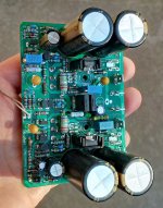
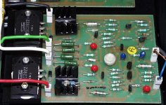
Looking at my populated board and comparing with the original board, we can see clearly how much different the clone components are. I'm following the PDF Algar posted some year ago so I'm getting new capacitors for C1-C12, and matching TR1+TR2.
Pictures are super big so zoom at your leisure.
My cloned board


The original board.

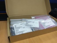
The new components from Element14 arrived today at my office. I've ordered all
transistors except TR7a TR8 (2N5087), TR11 TR12 (2SC2922)
capacitors except C13-C16
Might have jumped the gun too soon because I forgot to order better trimpots as well. Reading back I was reminded how some got faulty trimmers, and I've broken some trimmers by using a tiny extra bit of force.
I was hoping to order trimmers, 2N5087, and 2SC2922 from ebay store hiendparadise based in Turkey. I've inquired about the 2922 authenticity,
His listing photo seems genuine with plenty photos of the original packaging and matching HFEY on the transistors and box. But the heatsink at the back looks a little too shiny.
4 piece NEW SANKEN 2SC2922 GENUINE AUDIO TRANSISTOR FOR HI_END AUDIO ! | eBay
transistors except TR7a TR8 (2N5087), TR11 TR12 (2SC2922)
capacitors except C13-C16
Might have jumped the gun too soon because I forgot to order better trimpots as well. Reading back I was reminded how some got faulty trimmers, and I've broken some trimmers by using a tiny extra bit of force.
I was hoping to order trimmers, 2N5087, and 2SC2922 from ebay store hiendparadise based in Turkey. I've inquired about the 2922 authenticity,
Your previous message
Hello, I am sorry to ask this, is this original and genuine from SanKen Japan?
I am asking because someone sold me fakes.
Thank you very much.
You have a good day
New message from: hiendparadise Top Rated Seller(12,326)
Hi.Yes they are 100% genuine original items.I am an electronics engineer and we never buy and sell fake items.Please do not worry.Thank you and best regards Umit
Best Regards
Ümit
Customer Support:
+90 5384819695
His listing photo seems genuine with plenty photos of the original packaging and matching HFEY on the transistors and box. But the heatsink at the back looks a little too shiny.
4 piece NEW SANKEN 2SC2922 GENUINE AUDIO TRANSISTOR FOR HI_END AUDIO ! | eBay
Attachments
Have you included the output stage protection circuit? Some clones leave this out. Can't tell from the photos.
Edit: Going back and re-reading the early part of this thread I see I asked the same question some years (!!) ago. I just don't understand why DIYers omi output stage protection from their clone PCB layouts. If it was good enough for Naim....
Edit: Going back and re-reading the early part of this thread I see I asked the same question some years (!!) ago. I just don't understand why DIYers omi output stage protection from their clone PCB layouts. If it was good enough for Naim....
Hi
If anyone interesting about NAP 140 , i can provide PCB Power Amp and Regulator .
I layout PCB based on NAP 140 schematics and regulator ! Belows it's picture layout.
- Capacitor in based on Vishay axial tantanum cap
- NFB base on kemet tantan and pitch about 5mm for cap
- Layout for TO-3P Transistor like 2SC5200 or MJL3281A
- Pcb have modified option cap by pass power transistor.
Edit
You can chose 3 option
1. Full Kit : 2 pcb Amp + 2 pcb regulator - 30$ not include shipping ( EMS Shipping ).
2. PCB Power Amp only : 2 PCB Amp - 20$ not include shipping ( EMS Shipping ).
3. Regulator only : 2 PCB Regulator - 15$ not include shipping ( EMS Shipping ).
PCB: FR4 - 1.6mm
Copper : 2oz
Hot tin surface
Below it's some picture pcb i and my friend build !
Last edited:
As the maker of these Zerozone kits shows, the output transistors are attached direct to the case here but this will not allow heat to dissipate evenly enough to permit full power levels. Both the original NAP200 and Caowei kits show a long, thick bar section of about 30mm x 5 or 6mm aluminium fitted between the output transistors and the case bottom, as a heat spreader - This and similar construction, has been an integral part of the design of almost all NAP and Nait models since the beginning. This heat spreader bar is important if you wish to operate the amplifier anywhere near my estimate of about 30W power and above.
With just attachment to a thin aluminium case, the problem will be worse. Some Chinese manufactured cases are indeed 4mm thick and this is better but you will notice that the bottom plate is discontinuous, that is, it isn't folded to make full contact with the sides, front or back plates. All together, you can forget about a 200W/4R rating unless you do the heatsinking correctly. Yes, it probably will work OK with less responsive biasing control and at low power but it seems a waste of time and money to buy a high power amp but only build it to a low standard. I tested my build on 3mm aluminium at only 100W and believe me, the bottom plate was roasting hot in the area around the transitors, when I had to reduce the power to prevent damage.
Another issue is the mounting bar. Unless it is very thick or preformed to apply even pressure to each power transistor, it will bend under only slight clamping force and thus only apply pressure to the inner face (the area closest to the mounting bolt) of the transistors. As these are typically supplied with silicone washers, they will require plenty of even clamping force to provide reliable contact.
All together, this is why some builders run into problems with unsatisfactory operation when the kits are cheap and don't come with assembly advice, diagrams or appropriate components to complete them correctly. You always need to check the kits for how much more is really necessary to build and finish the amplifier than just look at the supplier's mock-up build and assume that is correct when really, it's only a basic assembly of the parts provided in a generic enclosure with little more than necessary to get it to testing level.
Always use the original amplifier as the guide to the critical requirements such as power supply and heatsinks, wiring locations etc. Both kit PCBs provide the VI limiter circuits on the board since the pattern is an accurate clone and the parts for these are shown fitted to penmarker's finished board in his pic.
As a matter of interest, most audiophiles are paranoid about the effect limiters may have on the their precious audio that can happen with poorly matched simple limiter circuits. However, these NAP200 limiters are dual slope types which follow the original amplifier's SOA curve more closely and in any case, few Naim users will ever turn their amplifiers up beyond a few watts in the home so this is step is taken in fear of the unknown and misunderstood rather than what will be reality for many audiophiles. I figure that if the amplifier is distorting noticeably on peaks, something else is wrong or the design just isn't big enough for your needs. As said, Naim have used limiters since the first model and you don't hear many original owners complaining - only the third and fourth owners or so, who tend to be less concerned about speaker damage and insurance risks.
Last edited:
- Home
- Amplifiers
- Solid State
- NAP-140 Clone Amp Kit on eBay