Cricklewood electronics
Smiley mentioned Cricklewood Electronics . I have put a link because some very unusual transistors are in stock ( even Mullard and some unnamed BDY 56 !!) . I imagine some even useful for these amps ( Ian ? ) . They have interesting valves also ( 6AM6 for example ) . No Crimson Kits alas .
Cricklewood Electronics - CCTV. CCTV Equipment. CCTV Systems. Digital CCTV Cameras
Last edited:
Hello Nigel,
Back in the 1977 the Cricklewood electronics was the only and most serious el. parts and top semis mail order shop avail. in the UK and one of the best in EU. I saw in that time theirs 200+ pages A4 catalogue with realy HiTech components (NOT EXOTIC !!) and all the needed parts for the Crimson Amp can be sourced there.
There was no Crimson kit availl. only the SCH diagram for the BJT SMxxx and Hita. LatFet ver of the 120 - 150W-8R Amplifier.
The guy in Wienna who make the amps for my friend got the SCH from his Radio-Amateur friend from UK. I'm not sure if the amps were sold commercially or were spreaded between the close friends only. ?. .
Latter I got all the parts from the Crimson man and make two amps for my self also with Hitachis
married with Mission 770, Naxo biamped + LP12-full pack . . . I was in mid heavens . . for years . . .
until I married Scintillas...

Back in the 1977 the Cricklewood electronics was the only and most serious el. parts and top semis mail order shop avail. in the UK and one of the best in EU. I saw in that time theirs 200+ pages A4 catalogue with realy HiTech components (NOT EXOTIC !!) and all the needed parts for the Crimson Amp can be sourced there.
There was no Crimson kit availl. only the SCH diagram for the BJT SMxxx and Hita. LatFet ver of the 120 - 150W-8R Amplifier.
The guy in Wienna who make the amps for my friend got the SCH from his Radio-Amateur friend from UK. I'm not sure if the amps were sold commercially or were spreaded between the close friends only. ?. .
Latter I got all the parts from the Crimson man and make two amps for my self also with Hitachis
married with Mission 770, Naxo biamped + LP12-full pack . . . I was in mid heavens . .
for years . . . until I married Scintillas...
NOS
to be very old stock to be authentic Fairchild products. The BDY56 seems to be only supported by Thomson CSF (ST-micro)
but as you say, we can't be sure who supplied them as ST don't list them any more. They appear from data sheets to be
simply a scaled down BDY58 die. However, I believe the BDY58 used by NAIM, to be Semelab product as was marked on the
semis in amplifiers I worked on and in my own NAP 140. Perhaps it did vary but it seems inconsistent with their usual concern
for supply consistency.
Has anyone acquired any of this stock and tried/identified their BDY56 items?
Thanks for that link, Nigel. It merits following up the sources of some of those parts. The ceramic/epoxy TO106 would haveSmiley mentioned Cricklewood Electronics . I have put a link because some very unusual transistors are in stock ( even Mullard and some unnamed BDY 56 !!)
to be very old stock to be authentic Fairchild products. The BDY56 seems to be only supported by Thomson CSF (ST-micro)
but as you say, we can't be sure who supplied them as ST don't list them any more. They appear from data sheets to be
simply a scaled down BDY58 die. However, I believe the BDY58 used by NAIM, to be Semelab product as was marked on the
semis in amplifiers I worked on and in my own NAP 140. Perhaps it did vary but it seems inconsistent with their usual concern
for supply consistency.
Has anyone acquired any of this stock and tried/identified their BDY56 items?
Feedforward
The BDY 94 looks interesting . They even have very high voltage germanium's . I had a concept amp to test feed-forward in mind ( Sandman ) . In theory Ft is not important with feed-forward ( germaniums will be about 200 kHz on a good day I guess , they probably have whiskered up by now ) . Tempting . The germanium's almost needs no bias voltage . I think someone said Ft 3khz for an early germanium and wasn't kidding .
http://digilander.libero.it/paeng/feedforward_concepts.htm

Thanks ! very interesting. It is best way to decouple power supply.
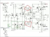
perhaps a problem of energy saving. V.A.S. (TR4-TR6) max Vp reach 40Vp
Power output Emitter follower (TR9-TR11) Gv < 1 can not exceed 40Vp but they are fed from 50Vcc
I also believe that addition of group rc has lowered slightly maximum power than original scheme.
Hi , I was just going to switch off for the day . The idea is to have any ripple in the 50 V supply well above the smooth supply . It is cheap to do .
There will be very complex ripple free PSU designs you could try . However consider how bad the usual arrangement is . Anything will be heaven by comparison . This simple idea is fast and quiet .
The amp will seem more powerful because it will maintain full 38.3 V . If you lift the zener on a red LED you can even have 40V .
Let me know if you do it and the sound .
Nigel
Hi Andrew . Ian and I were talking about how to improve this generally . Could you simulate it and see if we can keep what I've done . Personally I would remove VI limiting completely . looking at it I suspect it is OK ? Simple and cheap is what we look for . I think this idea is too good to reject . If people have a party fit 2 AF fuses in the speaker lines and keep some handy , they are not too bad and usually work . I would not without thought use extra RC filtering as talked about in the reply to my drawing as it will upset DC operating points if in the wrong places . D Self I think said 10 R max for that ( + 1000 uF ) ?
Ian and I were asking if the VI time lag operating point was realistic for modern demands ( sorry Ian if I truncate the conversation and add new thoughts , do forgive me if it was with someone else , I am not above that ) . This could be a very useful exercise .
Ian and I were asking if the VI time lag operating point was realistic for modern demands ( sorry Ian if I truncate the conversation and add new thoughts , do forgive me if it was with someone else , I am not above that ) . This could be a very useful exercise .
Better PSU
 [/IMG]
Thanks Andrew and so simple to do . I put in the 40 V LED mod as it is cheap . The resistor can be 470R as before ( 750 R if LED current unknown ) . Check maximum LED current ( usually 30 mA ) and if so 470 R is about right as it was before . The LED is a handy indicator that circuit is powered and shifts the voltage up about 1.8 V . Any red LED will do . The first unmarked caps shown at the start of voltage rail can be 0.1 uF and would be polyester 100 V types . Note Zener diodes are fitted in the opposite direction to normal diodes .
Thanks Andrew and so simple to do . I put in the 40 V LED mod as it is cheap . The resistor can be 470R as before ( 750 R if LED current unknown ) . Check maximum LED current ( usually 30 mA ) and if so 470 R is about right as it was before . The LED is a handy indicator that circuit is powered and shifts the voltage up about 1.8 V . Any red LED will do . The first unmarked caps shown at the start of voltage rail can be 0.1 uF and would be polyester 100 V types . Note Zener diodes are fitted in the opposite direction to normal diodes .

Thanks understood. I like this solution of decoupling.Hi , I was just going to switch off for the day . The idea is to have any ripple in the 50 V supply well above the smooth supply . It is cheap to do .
There will be very complex ripple free PSU designs you could try . However consider how bad the usual arrangement is . Anything will be heaven by comparison . This simple idea is fast and quiet .
The amp will seem more powerful because it will maintain full 38.3 V . If you lift the zener on a red LED you can even have 40V .
Let me know if you do it and the sound .
Nigel
I need only trim my beautiful gold plated red pcb

next weeks I hope to begin assembling some parts.
talk to you soon

Hi Nigel
I have read your posts in this discussion. Very interesting. I was surprised by his revelation, the secrets of Naim, the 22K resistor at the collector of the input differential pair. Thank you very much.
Now I wonder: Are there other secrets in the Naim?. In the post, 98, 99,100 is argued that there is a configuration error. The connection point between the positive output transistor and the resistance of 27R is incorrectly represented in the diagram. What is your opinion?
Attachments
Hi , I read your post and thought you were absolutely correct . If I send you the amplifier that possibly inspired the Naim ( Sinclair Z 30 which was a kit in 1969 ) you will see that the Naim is much better and almost modern . The Sinclair Neoteric which preceded it is a work of genius however not commercial ( it is said to be a design classic and might have inspired the Lecson ) . If you get it right I hope you will post the results .
If you use the design in Self you will have to recalculate as he gives examples for Darlingtons or CFbP ( Szikai ) . I don't remember for a Quasi complimentary design although I might be wrong ? The Naim is half Darlington and half Szikai . I would guess choose a resistor half way between his examples perhaps ? You will have to follow all of his advice if you want to benefit ( mount the Vbe multiplier transistor near the power transistor as he shows ) . I found the Sinclair stuff so here is for anyone who likes tech talk .
http://www.diyaudio.com/forums/solid-state/194744-very-first-blameless-amplifier-prior-1969-a.html
The advantage of doing it as you suggest is to make the initial switch on period better . After half an hour not much difference . To be honest Naim type amps do not draw much power and should be left to stay warm . I remember a man saying he would leave his girlfriend because she switched off his Naim amp . That will take a week to be right he said . I would say the Self circuit will account for fluctuations of power and room temperature better . If you do it please do a before and after bias check ( measure V of emitter resistors ) .I would like the before and after data for all to see if you can ( clip type test leads and over hours of use ) . Take readings when not playing music .
I have a name for the Naim . It is corrupted Blameless principle ( 22K ) . I approve of the corrupted part . Musically it is more correct .
If anyone wants to help me I am doing a project on the evolution of the blameless amplifier ( my private mailbox ) . I am saying the Naim is the first I know of which is in the pattern . Heath AA 1640 perhaps . Gogny 1964 is a starting point . Any you find will be interesting . All will have LTP input .
I should say this is a Thread about building NAP 140 Clone . Hope new people will ( you should ) .
Improving the Naim
First . If we are honest these are Naim inspired circuits . Julian Vereker told me no one can copy a Naim because the transformer design is special and other details . That is a bit like saying the AC Cobra car kits are nothing like an AC Cobra . Yes and no . However they are paying tribute to the design in both cases . If anyone reading this will never be a kit builder just go buy a secondhand Naim , it will almost certainly prove to be reliable . It will be an investment and will not loose money . That must tell you something ?
If you want to start a new thread invite me and I will come along . Call it the corrupted blameless amplifier or something . We can say we use ready made Naim clone PCB's as it saves investing in bespoke PCB's . We love Naim and it inspired a quest to make our own version . If no one comes to the thread we can invent another title until they do .
One thing will be to take out all of the compensation and protection and be responsible people and not party with the amps . You will be surprised how much we can take out and it will get better . I beg that you keep a clone to reference too . It is too easy to say a thing is better just because it's your own design . R/C question . I will answer that tomorrow if can . My next work project has turned up so I must get on with that .
R+C//R
There are plenty of text books that deal with the R+C//R compensation . Most require high level maths . I speculate that this was to get an amp without an output choke to drive Quad ELS 57 the reference speaker of Naim Audio 1971 . The Quad is a complex load . If anyone can find a Spice model for the Quads it might be fun to verify this . The striking thing is the R+C//R is not symmetrical ( nor is the output stage ) . This all looks like the work of a genius . Leave well alone I would say if asking . At the pub my friend suggested that these would have been set with a dummy load and square waves at ( 7 kHz I thought ) . In the Self type amp this would be a 100 R resistor .
There are plenty of text books that deal with the R+C//R compensation . Most require high level maths . I speculate that this was to get an amp without an output choke to drive Quad ELS 57 the reference speaker of Naim Audio 1971 . The Quad is a complex load . If anyone can find a Spice model for the Quads it might be fun to verify this . The striking thing is the R+C//R is not symmetrical ( nor is the output stage ) . This all looks like the work of a genius . Leave well alone I would say if asking . At the pub my friend suggested that these would have been set with a dummy load and square waves at ( 7 kHz I thought ) . In the Self type amp this would be a 100 R resistor .
- Home
- Amplifiers
- Solid State
- NAP-140 Clone Amp Kit on eBay