Hi Ruwe,
meanwhile i desoldered the mains and measured them, the C-B is about 560Ohm in one direction and closed in the other while C-E is closed in both directions. Those are defenitly gone. Desoldered and measured the TIPs the 0.22Ohm resistor and and the other transistors and they seem to be ok. I ordered the 2SC5200 , the TIPs and the 0.22 resistor now to be on the safe side. Lets see next week.
Regards haggyhug
Hi Ruwe,
meanwhile i desoldered the mains and measured them, the C-B is about 560Ohm in one direction and closed in the other while C-E is closed in both directions. Those are defenitly gone. Desoldered and measured the TIPs the 0.22Ohm resistor and and the other transistors and they seem to be ok. I ordered the 2SC5200 , the TIPs and the 0.22 resistor now to be on the safe side. Lets see next week.
Regards haggyhug
Hi,
When you say "closed", does it mean "short" or "open"? It's normal to have open between C-E in both directions. B-E and B-C should measure something in one direction and open in the other (like diodes)... but again, for power transistors it doesn't always mean 100% good.
Replacing them all is the easiest troubleshooting
")
Naim NAP140 clone - re-design
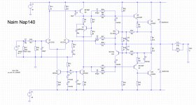
Sorry to open this threadie up again ....but ....I bought a couple of NAP140 Boards in curiousity; and something claiming to be a Mark Levinson design - but firstly with these so called NAIMs
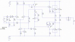
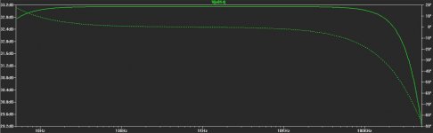
The circuit that came from China I checked with the board and I immediately asked - "why so many compensations in the design, what were they fighting against?". Is it phase correction to reduce X-over distortion? - Why so much HF filtering to prevent HF instability? Why all that spare capacitance to slug the amplifier down? We all know that using capacitors as "frequency dependent resistors" introduces phase angles and reactive impedances
So I sat down and did some maths - examining Xc = 1 over 2π FC - then doing the Rect/Pol conversion to find reactive impedance
Then began loading the circuit into into Spice to play with it.
I have to say the findings are a bit quirky and all these strange compensations doesnt enhance things very much
Sorry to open this threadie up again ....but ....I bought a couple of NAP140 Boards in curiousity; and something claiming to be a Mark Levinson design - but firstly with these so called NAIMs
The circuit that came from China I checked with the board and I immediately asked - "why so many compensations in the design, what were they fighting against?". Is it phase correction to reduce X-over distortion? - Why so much HF filtering to prevent HF instability? Why all that spare capacitance to slug the amplifier down? We all know that using capacitors as "frequency dependent resistors" introduces phase angles and reactive impedances
So I sat down and did some maths - examining Xc = 1 over 2π FC - then doing the Rect/Pol conversion to find reactive impedance
Then began loading the circuit into into Spice to play with it.
I have to say the findings are a bit quirky and all these strange compensations doesnt enhance things very much
Attachments
Last edited:
cleaned it up
What a minger
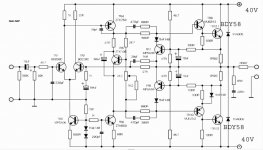
Now it's more efficient and i've thrown an enhancement idea in there if anyone (like me) who is running complex and demanding loads. Also took out all the phase compromises and claptrap outta there causing a wild load of phase shift for no apparent purpose other can causing unwanted harmonic and phase effects. Put my signature signal conditioning in at the front.
Given the input the proper reference current - took a different view of the feedback path along with it's DC quantity to deck via R21 for the bases of Q3-Q4 and lifted it above chassis with ground return.
Cleaned out the unnecessary. Put some thermal tracking via bias chain with a single diode D5 of which there are a range that could take that space -
the 1N4148 is all I had close as a model -
Improved the component list to modern day and some Motorola and Toshiba favorites/reliables. Cleaned out all the anti RF stability crud and kept it simple with c6.
Less components - more music - better thermal - less phase distortion - better dynamic range -- less sluggish in the bass - less colapse of range in the treble through all that unnecessary filtering, and as long as the PSU has enough uumph ... more capable on difficult loads (Cambridge Audio R50's - KEF 102/4 Reference - Linn Ice Bricks (Isobarik) etc.
Oh I made it more efficient too -- it was burning off energy for no purpose
What a minger
Now it's more efficient and i've thrown an enhancement idea in there if anyone (like me) who is running complex and demanding loads. Also took out all the phase compromises and claptrap outta there causing a wild load of phase shift for no apparent purpose other can causing unwanted harmonic and phase effects. Put my signature signal conditioning in at the front.
Given the input the proper reference current - took a different view of the feedback path along with it's DC quantity to deck via R21 for the bases of Q3-Q4 and lifted it above chassis with ground return.
Cleaned out the unnecessary. Put some thermal tracking via bias chain with a single diode D5 of which there are a range that could take that space -
the 1N4148 is all I had close as a model -
Improved the component list to modern day and some Motorola and Toshiba favorites/reliables. Cleaned out all the anti RF stability crud and kept it simple with c6.
Less components - more music - better thermal - less phase distortion - better dynamic range -- less sluggish in the bass - less colapse of range in the treble through all that unnecessary filtering, and as long as the PSU has enough uumph ... more capable on difficult loads (Cambridge Audio R50's - KEF 102/4 Reference - Linn Ice Bricks (Isobarik) etc.
Oh I made it more efficient too -- it was burning off energy for no purpose
Attachments
What you end up with is basically a self blameless, the nap was designed like that because apparently it has a particular sound and from what I see a lot of people liked it.
I was reading a review of current naim amps the other day and in one review it was stated that naim still uses the same old nap250 circuit in one of their current amps and this was testemony for the quality and sound of their amps. I was highly susrprised and have been trying to verify this but now Ive lost the link to the review as well as I accidently cleaned the browsing history. The nap250 is basically this nap140 with more output trannies. Interesting if the writer of that review is correct..........
I was reading a review of current naim amps the other day and in one review it was stated that naim still uses the same old nap250 circuit in one of their current amps and this was testemony for the quality and sound of their amps. I was highly susrprised and have been trying to verify this but now Ive lost the link to the review as well as I accidently cleaned the browsing history. The nap250 is basically this nap140 with more output trannies. Interesting if the writer of that review is correct..........
Less components - more music - better thermal - less phase distortion - better dynamic range -- less sluggish in the bass - less colapse of range in the treble through all that unnecessary filtering, and as long as the PSU has enough uumph ... more capable on difficult loads (Cambridge Audio R50's - KEF 102/4 Reference - Linn Ice Bricks (Isobarik) etc.
Hi,
Interesting thoughts and ideas! I just didn't understand are you listening to this amp, or your design is a result of simulation only? ... In my experience the simulation rarely represent the reality ... The original design is not overcompensated. I could easily make it oscillate with slightly capacitive speaker cables. So, I guess the R/C groups are a necessity.
Why such a big inductance at the output? Is there any specific reason? ... The original schematics doesn't have any, the revised kit versions are using no more than 1uH//10-15 ohms.
Regards
I have two boards -- I've decided for the interest of my curiousity to build the old variant on one - and the proposed simplified version on the other. Simulation can only show an indicative model - a lot could come out of final experimentation by physically testing and researching through the differences. Those R/C groups may have been a necessity in the day it was designed. With a phisical examination - we'll see what's what.
But like Bruce Lee and his "Tao of Jeet Kune Do" - get rid of the waste and strip back to essentials
Last edited:
Speaker protection
Hello
I built my Naim clone after the Avondale NCC200 schematic .
All I can say is a great amp , I had before the Ebay kit but these has far better sound .
I have only one big problem !
When I turn off the amplifier and the power goes done at the PS capacitors when it reach around 10V the power stage open up and 6-7VDC goes out on the speaker terminal.
I would like to avoid to the DC voltage destroy my speakers .
Can someone suggest a good quality speaker (DC) protection ?
I need something simple so I do not need to break the bank .
Also have to be reliable and minimal or no effect (downgrade) on the amplifier sound .
Thank you
Cheers
Hello
I built my Naim clone after the Avondale NCC200 schematic .
All I can say is a great amp , I had before the Ebay kit but these has far better sound .
I have only one big problem !
When I turn off the amplifier and the power goes done at the PS capacitors when it reach around 10V the power stage open up and 6-7VDC goes out on the speaker terminal
.I would like to avoid to the DC voltage destroy my speakers .
Can someone suggest a good quality speaker (DC) protection ?
I need something simple so I do not need to break the bank .
Also have to be reliable and minimal or no effect (downgrade) on the amplifier sound .
Thank you
Cheers
Attachments
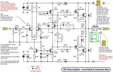
Ncc200
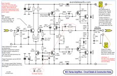
I believe the circuit is updated - see this webpage:
Audiophile Power Amplifier modules from Avondale Audio : avondale audio
Circuit attached.
I believe the circuit is updated - see this webpage:
Audiophile Power Amplifier modules from Avondale Audio : avondale audio
Circuit attached.
Attachments
PhaseLockLoopy,
Keep us posted. It's interesting to know the result of your changes. The Douglas Self's book has a lot of information about this same basic schematic, and lots of developments and improvements. Still, I read sometimes mixed reviews about his "Blameless" amp. I'm very curious though!
Keep us posted. It's interesting to know the result of your changes. The Douglas Self's book has a lot of information about this same basic schematic, and lots of developments and improvements. Still, I read sometimes mixed reviews about his "Blameless" amp. I'm very curious though!
Hello
Zabadac you posted the same circuit I did before !
These need DC protection !
When I turn it of after 1 minute I can measure 6-7DCV on the speakers terminal.
Otherwise sound great and works great . Of course I tested 4 different power transistors a lot of other parts . It is really sensitive to almost all parts it use .
I played over two weeks testing , testing and more testing new parts .
Greets
If it is a switch off issue - soft start circuit (depending on the relays you chose - 2x DPDT can double to disconnect the speakers at the point of switch off and on at the point
so Soft start relay is timed at say 800mS
and speaker relay 100mS behind that
though at switch off the speaker relay will drop first
no complex DC measurement or balanced rail comparator
though even this may not be inexpensive in parts or time.
A crowbar circuit is relatively cheap- but I personally have never liked them
the good old triac across the speaker outs to create a short circuit I've always thought of as madder than my avatar.
Very nice! I have those too and I am very happy with them.
I thought I might help see this thread continue so I have just ordered the naimclones. Will report back once I know what ones they are (hoping they are the avondale copies). I recently completed two of the Goldmund clones. Superb amps. It will be interesting to compare with the naim.
Well I built the clones. They are the original Avondale types. All went well and they work. Just one problem. I'm supposed to set 6-10mv accross the 0.22ohm resistor but all I get is 0.5mv and adjusting the pot doesn't alter it. (meter set on 200mv dc) If anyone out there can help me I would be most obliged. Please explain like you are talking to a monkey.
Cheers Jan, I never realised these pots turn so far. I was afraid I was giving it a big dose of dc and not able to measure it. It sounds great now. Thanks very much for your quick and helpful reply. My next question is a general one realy. I don't know if a pre-amp is neccessary. I never used one on my gainclones or goldmund clone, and although the naimclone sounds good would a pre-amp improve it. (I see their is even a naimclone pre-amp on ebay) Does impedance matching do anything these days. Comments very welcome. Regards Barry
- Home
- Amplifiers
- Solid State
- NAP-140 Clone Amp Kit on eBay