John65b,
The AKSA does exactly what the designer intended - gives a "rose tinted" sound. The NAP140 clone sounds very Naim-like to me.
I prefer the pukka NCC200s and my Leach low TIM to both.
I have not tried a P101. I gave up with MOSFETs some time ago (although my GB150s suit my kitchen system very well).
BTW one of the worst amps I ever built was an Aleph 3 clone - what a waste of energy!
Dave.
Blown up NAP140 clone
I got my amps working this weekend - yet to be assembled with a decent psu into a case so cannot yet comment on how they sound. However, some observations:-
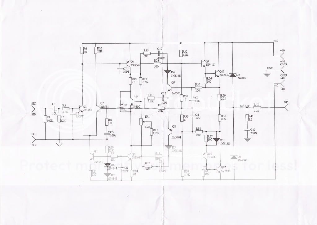
If Q5 goes open circuit, the drive to the output transistors will be huge and turn them on maximum - this would definately blow them up and a few peripheral components to - like the pre-drivers. The current limiting transistors Q7 & Q8 should stop this except for the fact that C3 and C4 will appear as a short when the surge starts and thsi will ensure that Q7 & Q8 are off instantaeously. As the C3/C4 capacitors charge up, Q& & Q8 will turn on and then limit the output drive - but this is almost certainly too late to prevent damage.
Therefore Q5 is very important - I would strongly recommend using the TIP41 and mounting it on the heatsink to compensate for thermal runaway. Also, from memory this weekend, the legend on the PCB is also incorrect for Q5 - I checked the PCB tracks before deciding where to connect 3 flying leads from the PCB to the offboard TIP41.
The multi-turn blue bias pot increases bias current when turned clockwise and decreases it when turned anti-clockwise.
I have found that you need to me even more careful than historically with these new silver solders. One of my power transistors appeared to be soldered good, but when I put a meter on the leg above board and checked connectivity below board there was an open circuit. I would suggest very careful inspection with a magnifying glass and a good light. I stress - any open circuits around the bias transistor and its associated components will blow the amp up.
Hope this helps
Chris
I got my amps working this weekend - yet to be assembled with a decent psu into a case so cannot yet comment on how they sound. However, some observations:-
If Q5 goes open circuit, the drive to the output transistors will be huge and turn them on maximum - this would definately blow them up and a few peripheral components to - like the pre-drivers. The current limiting transistors Q7 & Q8 should stop this except for the fact that C3 and C4 will appear as a short when the surge starts and thsi will ensure that Q7 & Q8 are off instantaeously. As the C3/C4 capacitors charge up, Q& & Q8 will turn on and then limit the output drive - but this is almost certainly too late to prevent damage.
Therefore Q5 is very important - I would strongly recommend using the TIP41 and mounting it on the heatsink to compensate for thermal runaway. Also, from memory this weekend, the legend on the PCB is also incorrect for Q5 - I checked the PCB tracks before deciding where to connect 3 flying leads from the PCB to the offboard TIP41.
The multi-turn blue bias pot increases bias current when turned clockwise and decreases it when turned anti-clockwise.
I have found that you need to me even more careful than historically with these new silver solders. One of my power transistors appeared to be soldered good, but when I put a meter on the leg above board and checked connectivity below board there was an open circuit. I would suggest very careful inspection with a magnifying glass and a good light. I stress - any open circuits around the bias transistor and its associated components will blow the amp up.
Hope this helps
Chris
Re: Blown up NAP140 clone
As good a reason as any for NOT using silver solder.
I still have 2 full rolls of 60/40 lead solder.
Andy
cdswift said:
I have found that you need to me even more careful than historically with these new silver solders. One of my power transistors appeared to be soldered good, but when I put a meter on the leg above board and checked connectivity below board there was an open circuit.
As good a reason as any for NOT using silver solder.
I still have 2 full rolls of 60/40 lead solder.
Andy
Seller message
I ordered the kit a couple of days ago and got a reply from the seller saying that:
"Please take care about the pin out of Q1 & Q2. It is not matched with silk screen of PCB. Please see the photos in my listing. You should mount the Q5 on the power transistor or heatsink. Take care about the polarity of the transistor. Ignore the silk screen printing and follow the circuit diagram."
Also I was wondering if it would be worth the trouble to match the transistors for fhe and vbe (basic DMM way). Any ideas on that?
Re: Seller message
Other posters (including myself) have noted a small DC offset voltage at the output (mine is 70mv). I found a reference here: http://bbs.hifidiy.net/viewthread.php?tid=48492&extra=&page=8
that recommends selecting an hfe for TR1 that is greater than TR2 to address this.
ratchet said:I ordered the kit a couple of days ago and got a reply from the seller saying that:
"Please take care about the pin out of Q1 & Q2. It is not matched with silk screen of PCB. Please see the photos in my listing. You should mount the Q5 on the power transistor or heatsink. Take care about the polarity of the transistor. Ignore the silk screen printing and follow the circuit diagram."
Also I was wondering if it would be worth the trouble to match the transistors for fhe and vbe (basic DMM way). Any ideas on that?
Other posters (including myself) have noted a small DC offset voltage at the output (mine is 70mv). I found a reference here: http://bbs.hifidiy.net/viewthread.php?tid=48492&extra=&page=8
that recommends selecting an hfe for TR1 that is greater than TR2 to address this.
hoka said:Blew it up again! after replacing most of the components, no luck on the second try. This time I fried R 35. at least that is where the smoke came from.
I'm about ready to give up on these boards
A few suggestions:
1. use 1-2amp fuses on the +/- 35Vdc power supply.
2. use a variable transformer at the main and slowly increase the voltage, eg apply say 1/3-1/2 of the main voltage and measure relevant/key bias voltages on resistors and transistors. that way you can quickly detect incorrect orientations of transistors or incorrect values of resistors.
cheers.
hoka said:Blew it up again! after replacing most of the components, no luck on the second try. This time I fried R 35. at least that is where the smoke came from.
I'm about ready to give up on these boards
Hoka, did you also reverse Q5 as cdswift suggested? I checked on my boards (blue version) and the silkscreen is indeed wrong.
- Home
- Amplifiers
- Solid State
- NAP-140 Clone Amp Kit on eBay