Re: Polarity of DC blocking input capacitor
Andy, why do you say that the connection point between the positive output transistors and the 27R resistor is incorrectly represented on the schematic?
Is it because the original NAP140 was like this, or is it because Douglas Self says it should be like this? I haven't checked my new PCBs to see how they are wired.
To my eyes, either connection would work - I'm just not sure which would be better from a stability or performance point of view.
Regards
Chris Swift
Is it because the original NAP140 was like this, or is it because Douglas Self says it should be like this?
My amplifier design knowledge is partly influenced by John Linsley Hood (JLH).
JLH employed that realization I drew.
I don't know how exactly Naim did it in their original amplifiers.
Redid the speakers wiring so the returns were independant going back to the cap cenre point, and also removed the inductor/resistor part of my psu board. I got my bass back!!!
I really liked what that amp was doing but felt the bass was a bit lacking, away must have been to do with somthing i changed, i imagine the psu mods are the most likely source though it hard to say. Very happy now, though i am waiting for some wet 47uf tants for the feedback so see how they sound in there.
I really liked what that amp was doing but felt the bass was a bit lacking, away must have been to do with somthing i changed, i imagine the psu mods are the most likely source though it hard to say. Very happy now, though i am waiting for some wet 47uf tants for the feedback so see how they sound in there.
Silk Screen legend is wrong!
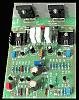
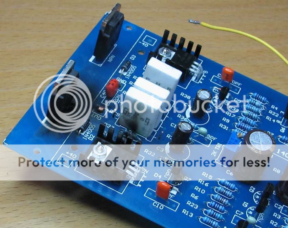
I was building my NAP140 clone this weekend and when matching my 2n5551 transistors for hfe, noticed that the legend for Q1 & Q2 the long-tailed input pair is incorrect on my board. The transistors need to be rotated thru 180 degrees so that the device is opposite to the outline printed on the board.
Anyone else notice this?
Also, there is no provision for an output inductor in this design. Has anyone built this version (see attached picture)? If so, does it work OK without inductor?
Regards
Chris
Attachments
Re: Silk Screen legend is wrong!
This is supposed to be a NAP140 clone so it would not use an output inductor. Naim beleives the inductance of the speaker wire should fill this function. If you use NACA5 (or NACA4 or Avondale's wire or older Linn wire) this will work to your advantage-- one less high voltage component. Most wire works just fine actually, so long as it is fairly ordinary and at least 3.5m in length. NACA5 is really very good sounding and a lot of people swear by Avondale's Black Link.
As for the backward transistor... I noticed this in the Ebay picture of the built PCB. I took it as an indication that one should be very careful and thoughtful when building these up. I am still waiting for my boards to arrive but, if anyone has noticed any other potential pit-falls, the warning would be much apreciated.
cdswift said:I was building my NAP140 clone this weekend and when matching my 2n5551 transistors for hfe, noticed that the legend for Q1 & Q2 the long-tailed input pair is incorrect on my board. The transistors need to be rotated thru 180 degrees so that the device is opposite to the outline printed on the board.
Anyone else notice this?
Also, there is no provision for an output inductor in this design. Has anyone built this version (see attached picture)? If so, does it work OK without inductor?
Regards
Chris
This is supposed to be a NAP140 clone so it would not use an output inductor. Naim beleives the inductance of the speaker wire should fill this function. If you use NACA5 (or NACA4 or Avondale's wire or older Linn wire) this will work to your advantage-- one less high voltage component. Most wire works just fine actually, so long as it is fairly ordinary and at least 3.5m in length. NACA5 is really very good sounding and a lot of people swear by Avondale's Black Link.
As for the backward transistor... I noticed this in the Ebay picture of the built PCB. I took it as an indication that one should be very careful and thoughtful when building these up. I am still waiting for my boards to arrive but, if anyone has noticed any other potential pit-falls, the warning would be much apreciated.
SanKen
I've heard a few amps based on the SanKen transistors including a brief period when Naim used them in the NAP140 (Late 80's? Early 90's?). I liked them alot. Comparing SanKen 140 to a 140 using the proprietary Naim 002 transistor I thought the SanKen amps were a little warmer, friendlier and a little more fun. That's entire subjective though.
Flappytango said:Just got my kit .
I got pretty blue boards (NAP140C version) but did not get the toshiba transistors...
my transistors look very similar to the ones in post #7 of this thread and are labeled as follows.
SK
C2837
7N P
Does anyone know if these will work? Are they are equivalent tosh transistors that have been coming with these kits?
thanks
I've heard a few amps based on the SanKen transistors including a brief period when Naim used them in the NAP140 (Late 80's? Early 90's?). I liked them alot. Comparing SanKen 140 to a 140 using the proprietary Naim 002 transistor I thought the SanKen amps were a little warmer, friendlier and a little more fun. That's entire subjective though.
NAC 42
I'm considering buying the NAP140 kit and it only seems natural to add a Naim Preamp circuit. Has anyone else considered this PC board?: NAC 42 PC Board on eBay
Other than Naim preamps, what are people using with this amp?
I'm considering buying the NAP140 kit and it only seems natural to add a Naim Preamp circuit. Has anyone else considered this PC board?: NAC 42 PC Board on eBay
Other than Naim preamps, what are people using with this amp?
Another PCB error
If you are building the latest (blue) version of this clone, beware of another problem I discovered today. The main ground connection to the board (close to the input transistors) doesnt connect to anything except the zobel capacitor. The board will not set up properly unless the ground is also connected to the signal ground point (which it would normally do when all connected up). I corrected this omission by adding a wire link between these 2 points on the track side of the PCB.
Hope this helps someone
Regards
Chris Swift
just blew up two of these:
An externally hosted image should be here but it was not working when we last tested it.
just blew up two of these
How did you blow them up - was it whilst setting the bias? My recommendation if you can get your hands on one is to power them (one at a time) via a variac (variable mains transformer) and slowly increase the mains voltage whilst watching & adjusting the bias current - keep it down at 5ma until full mains voltage is reached and then increase the bias up to the desired level.
Whilst I was doing this, I noticed that at a certain point the bias current shot up off the scale - if I had not been controlling the voltage on the output transistors, they would probably have gone up in smoke. In the event, all I did was wound the mains voltage back down a bit and the re-adjusted the bias current downwards before starting to increase it again.
Re: just blew up two of these
Can you set the pot to the lowest setting before powering up? If my memory serves me right, there is a bias pot.
Once full power is applied, wait for a while eg half to one hour for the power transistor't's temp to settle down(stabilise) then adjust the pot to the reqd. bias current. Is is possible?
cdswift said:How did you blow them up - was it whilst setting the bias? My recommendation if you can get your hands on one is to power them (one at a time) via a variac (variable mains transformer) and slowly increase the mains voltage whilst watching & adjusting the bias current - keep it down at 5ma until full mains voltage is reached and then increase the bias up to the desired level.
Whilst I was doing this, I noticed that at a certain point the bias current shot up off the scale - if I had not been controlling the voltage on the output transistors, they would probably have gone up in smoke. In the event, all I did was wound the mains voltage back down a bit and the re-adjusted the bias current downwards before starting to increase it again.
Can you set the pot to the lowest setting before powering up? If my memory serves me right, there is a bias pot.
Once full power is applied, wait for a while eg half to one hour for the power transistor't's temp to settle down(stabilise) then adjust the pot to the reqd. bias current. Is is possible?
I did not even have the time to get a reading on the bias, everything blew in a split second. My PSU is ok, so I have no idea what went wrong I measured every resistor before soldering and took extreme care in putting the thing together.
Is there anyone who has got the "new and improved version" working?
I am trying to figure out what went wrong and what the extend of the damage is, how do I get pictures uploaded? then someone might be able to diagnose the boards.

Is there anyone who has got the "new and improved version" working?
I am trying to figure out what went wrong and what the extend of the damage is, how do I get pictures uploaded? then someone might be able to diagnose the boards.
Were Q1 and Q2 in the wrong way around, i.e the correct way since they are marked wrong wrong on the layout.
if you look at that you can see that Q1 and Q2 need to be reversed compared to the outlines on the boards. Also the Gnd connectoins appears to be marked wrong as someone else has said. The SG, signal gnd has another hole net to it which would probably be the best place to take your gnd back to the psu. And the GND should probably be taken to that point as well. Its a bit weird. Maybe look at the chinese thread for these boards will help:-
http://bbs.hifidiy.net/viewthread.php?tid=48492&extra=&page=8
Phil
An externally hosted image should be here but it was not working when we last tested it.
if you look at that you can see that Q1 and Q2 need to be reversed compared to the outlines on the boards. Also the Gnd connectoins appears to be marked wrong as someone else has said. The SG, signal gnd has another hole net to it which would probably be the best place to take your gnd back to the psu. And the GND should probably be taken to that point as well. Its a bit weird. Maybe look at the chinese thread for these boards will help:-
http://bbs.hifidiy.net/viewthread.php?tid=48492&extra=&page=8
Phil
There are two revs, not sure which is which now as these look the same but just a different colour?
Anyway Hoka, you've made a damn fine job of blowing that up, right through those components to the output.
You sure nothing was shorted?!
Its a real shame that you have done both boards but might help you fix it as it must obviously be a common fault you have made.
Not just a wiring fault is it?
Anyway Hoka, you've made a damn fine job of blowing that up, right through those components to the output.
You sure nothing was shorted?!
Its a real shame that you have done both boards but might help you fix it as it must obviously be a common fault you have made.
Not just a wiring fault is it?
I am about 95% sure the white and blue pictured above (long boards) are the same. The ealier smaller boards are a very different layout and there are more like a NCC200 rather than a Nap140. I have just bought 4 of these boards of a chap on another forum. Not sure what to do now since is seems people are having issues with these newer ones.
Richie00boy -
I think I have seen amp boards that attain max bias current at min resistance on Bias pot, so should this be identified first?
Since I do not have a variac, I always try to significantly drop voltage (a big monster series resistor ) on rails and then check for smoke, Then turn the bias pot to see which direction the bias moves and reduce as much as possible before putting full voltage on rails.
- Home
- Amplifiers
- Solid State
- NAP-140 Clone Amp Kit on eBay