Does increasing the input LTP tail current and reducing the collector/drain load value result in a lower open loop gain?
Thanks for querying this Andrew. My post was a restless late at night effort that I should have left till morning.
The LTP is a minor player in the loop gain stakes and I should have looked elsewhere. That said, lowering the collector load of TR1 from 1k to 270R would reduce stage gain on the other hand increasing the standing current (and Gm) would do the opposite.
Roughly there is a quartering of the first of these factors and a fourfold increase in the second and these square off against one another.
TR1 still has to contend with it's partner TR2 working in phase opposition which halves the gain it would deliver as a common emitter amplifier and so deliver into the Vas stage load in parallel with the 270R collector resistor.
In the Vas stage, the increase of the CCS load resistor from 62R to 68R reduces the standing current from 10 mA to 9 mA which will reduce the Gm factor (and open loop gain) slightly.
The additional input RC filter of 1k and 10 pF is interesting. I remember a comment about the need - possibly a Hifi News review of an Audiolab amplifier some years ago. The theory for this was r.f. could get through a simple RC filter and the albeit small additional filtering prevented that.
howarthcd excellent discovery for the HDMI cover. I went a slightly more extensive wayPictures to follow...
Thanks
SB
Please if you have time, it would be good to see your solution.
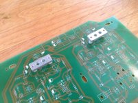
Regarding the heatsinking of the 2SC2922s, I've just ordered 20mm square and 1/2" square aluminium bars, both 200mm long. The 20mm will sit between the output devices and the case's bottom panel, the 1/2" will clamp the devices down onto the 20mm bar. I'm intending on using 20mm PCB standoffs, so this should all fit together quite nicely.
I like your transformer choice, just wish that there was something similar over here as I would really have preferred one unit per channel. Yours are a good price too.
Chris
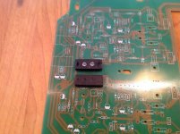
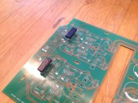
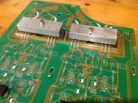
Here my own version of the LTP thermal coupling, piece of aluminum, then a little piece of alu tape on top. Then black paint. It will cover the LTP transistor pair, and fix the pcb with screws and standoff.
Attachments
Mjona what do you think is the TR1 TR2 bias current in the NAP200 circuit, and do you think the NAP140 difference of about 10% HFE mismatch in TR1 & TR2 (TR1 being higher) to give the 'Naim sound' still apply here?
Re LTP balance - static dc conditions and inward and outward transistor currents. The base region is very small and most of the current from the emitter rushes past the base and ends up at the collector.
The ratio of IC/IE or Alpha = Beta (HFE)/Beta (HFE)+1. For a HFE figure of 50 that means 98%.
BC239C transistors range in current gain from 380 to 800. The median figure of 590 would result in 99.83 % of the emitter current reaching the collector and a 10% increase from 590 to 649 would increase that ratio to 99.85.
Measuring the voltage drops across collector resistor will tell how much current passes to the supply rail, however there are other paths such as the Miller capacitance paths between collector and base terminals. Also the Vas is a load on TR1 collector.
The dominant compensation around the Vas stage is in the forward signal path followed by a four element switching stage followed by a reactive speaker load.
There is a small amount of lead compensation in the feedback loop but even with a stopper resistor this provides a more direct path to TR2 and a base emitter junction can be a rectifier at rf.
As I see it TR2 is in a position where it can provide some filtering effect against spurious input signals due to switching. The Miller capacitance can be manipulated by the choice of collector resistor value to reduce the collector voltage. This changes the internal boundaries between the collector and the base and increasing the capacitance to allow an expanded path for current to flow between the two points. I believe Naim have varied this strategy depending on output transistor fT as mentioned in my recent post.
Returning to the question of matching TR1 and TR2 the LTP should have a reasonable degree of balance. In theory these should conduct about 1.8 -1.9 mA apiece.
I see the NCC200 circuit - post 1492 on page 150 recommends TR1 should have higher gain than TR2. You might like to read what Dave S had to say in post 1419 about his experiences with this circuit.
Here my own version of the LTP thermal coupling, piece of aluminum, then a little piece of alu tape on top. Then black paint. It will cover the LTP transistor pair, and fix the pcb with screws and standoff.
For some reason I remember the term "Quiet Room" being used in relation to the NAP500 power amplifiers, which raises the question of whether the housing is as much about micro-phonic effects as temperature matching.
The VAS transistor B-E "regulates" the TR1 collector resistor voltage. As I've said before the LTP currents are well matched in the Naim circuit.
This can be looked at from the viewpoint of the base current required from TR1 collector current to drive the Vas transistor.
There should be roughly 1.85 mA available flowing through TR1 collector and the voltage across this needs to be sufficient - I recall your mentioning somewhere a figure of 0.5 base volts for this particular ZTX device, so as far as the Vas static conduction is concerned, the voltages and currents in that light would be all square.
Data sheets for the ZTX Vas transistor indicate a current gain of 200 or more, if it runs hotter due to the level of collector current that would increase that figure. The need for this section is to output 9 mA of standing current. Allowing a little leeway that might require a base current between 0.04 and 0.06 mA.
These amounts are a few percent of TR1 standing current.
It will be interesting to see the results when people complete their NAP200 clone projects but then those with earlier NAP 140 clone versions might be tempted into a conversion update.
I'm very pleased to see this. Often books skip through this section of an amplifer very quickly. I suspect it is by far the most important area of debate and will be good training for all similar amplifiers ( that's most ). This circuit started in 1957 and evloved about 1969. Even now it is little understood. Naim found this little trick and it should be preserved.
Andrew. From valves we always said the gain of a LTP is about 50 % the single side ( Rc/ [re+Re] ). Looking at the Naim LTP it possibly has higher gain than we imagine ( [ gain 1 + gain 2] /2 ? ) . In relation to the VAS gain no big deal.
Andrew. From valves we always said the gain of a LTP is about 50 % the single side ( Rc/ [re+Re] ). Looking at the Naim LTP it possibly has higher gain than we imagine ( [ gain 1 + gain 2] /2 ? ) . In relation to the VAS gain no big deal.
Here my own version of the LTP thermal coupling, piece of aluminum, then a little piece of alu tape on top. Then black paint. It will cover the LTP transistor pair, and fix the pcb with screws and standoff.
Аs I recommended.
As the Naim has different current through the LTP heat coupling will not do much. No harm in trying.
One very odd idea would be to heat one transistor more than the other. It might work. As long as offset is < 100 mV don't give it a second thought. A resistor could be all it needs. Please don't bother to try this.
One very odd idea would be to heat one transistor more than the other. It might work. As long as offset is < 100 mV don't give it a second thought. A resistor could be all it needs. Please don't bother to try this.
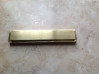
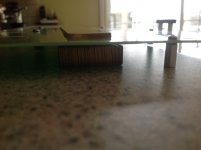
Heatsink issue solved, nice bar of brass, cut to fit
But brass is way harder to cut than aluminum. It was very work intensive with a limited tools I had.
Looking good, that must have taken you a while!
Nice.
Out of curiosity I've just checked and the thermal conductivity of brass is about half that of aluminium.
Are you planning on using the amp at high power? Just wondering whether the brass will be able to conduct heat away from the output devices quick enough to support higher power outputs.
True... so you'll run into problems at approximately 1/3 of full power where thermal load is at it's maximum.Brass has very bad thermal conductivity!!!You will have problems.Better use copper or aluminium.
Actually you'll have to lower the supply voltage when thermal conductivity decreases.
I don't believe the short thermal path that exists between the transistor backplate and the relatively thin case, will make any great difference in the overall cooling rate. The main bottleneck is the case thickness, particularly in the area close to the heat spreader bar. The brass bar, even if the conductivity is half that of aluminium, will be much more efficient at heat transfer than the 3mm aluminium sheet it is attached to. You won't change that thermal resistance even with direct mounting.
Each amplifier is rated for a maximum 100W/4R and presumably 60W/8R - no big deal for a low bias (~ 30 mA) amplifier so there is not a great deal of heat to dissipate in normal use. There certainly isn't a need for scaremongering about reducing power or other pointless measures.
Each amplifier is rated for a maximum 100W/4R and presumably 60W/8R - no big deal for a low bias (~ 30 mA) amplifier so there is not a great deal of heat to dissipate in normal use. There certainly isn't a need for scaremongering about reducing power or other pointless measures.
Ok good. I saw that brass thermal conductivity was half of the alu, but I had the bar in stock, and I knew that this amp doesn't heat that much, compare to a class-A (like my PassLabs amps).
No I was not planning to use this amp at high power. I always listen to rather low volume, maybe 1-5W. The rest of the power reserve is there just for that, a reserve for music transient. My days of listening to Ozzy Osborne at head banging levels are long gone
That bring me to the subject of this amp bias adjustment.
Is it 30ma as you suggested?
Thanks
SB
Last edited:
Ok good. I saw that brass thermal conductivity was half of the alu, but I had the bar in stock, and I knew that this amp doesn't heat that much, compare to a class-A (like my PassLabs amps).
Has your case arrived yet? Just wondering what the quality of construction is like. Mine should hopefully be here tomorrow, it seemed to have suffered a delay in Italy as it should have arrived on Friday last week.
Chris
- Home
- Amplifiers
- Solid State
- NAP-140 Clone Amp Kit on eBay