Funny you should say that as some say the Naim sound is because no inductor fitted. Geoffrey Horn was surpprised how much he prefered the Naim 250 to the Quad 405 via Quad speakers we now call 57's. Being that Geoff was a very technically gifted reviewer he speculated that the lack of inductor was the key difference. That is a strange idea seeing as the 405 is a very different animal to almost all other amplifiers. He removed what the 405 had and used 0R22 in it's place. From then on he thought they sounded much the same. The Naim cable was the inductor. Naim strongly discouraged other cables. This was not so much as to promote their own as a real requirement. 2.5 mm 50 strand copper twisted 2.5 turns per metre was Nains recomendation if not using NACA5 . I found DNM to be suitable and to me better. Woven or coax are in standard form not ideal. QED 79 or generic if split and twisted the 2.5 per metre would suit.
Nigel Pearson, i am afraid of telling anything further from the sound view  , waiting for some decent speakers first.
But, the damping idea came from a buddy who also follow's Douglas Self book while building hes own amps to hes sound liking, he doesn't believe in magic either
kclusa@yahoo.co,
I don't understand, why u have less low and high frequency with front-end decoupling caps ? Maybe the lack of bypass 220uF caps ? I did solder 100nF WIMA FKS 63VDC small caps under the board for bypassing, that might be the answer for missing high frequencies.....
I use even an input cap (Tantalum, measures 11.8uF) 35V rated cap and the sound is so juicy Feels like everything is there.
, waiting for some decent speakers first.But, the damping idea came from a buddy who also follow's Douglas Self book while building hes own amps to hes sound liking, he doesn't believe in magic either
kclusa@yahoo.co,
I don't understand, why u have less low and high frequency with front-end decoupling caps ? Maybe the lack of bypass 220uF caps ? I did solder 100nF WIMA FKS 63VDC small caps under the board for bypassing, that might be the answer for missing high frequencies.....
I use even an input cap (Tantalum, measures 11.8uF) 35V rated cap and the sound is so juicy
Feels like everything is there.http://www.sg-acoustics.ch/analogue_audio/power_amplifiers/pdf/audio_power_amp_design_comments.pdf
I read this recently. I would love to build example No 4 one day on page 6. I have a hunch it will sound very good.
I read this recently. I would love to build example No 4 one day on page 6. I have a hunch it will sound very good.
Naim did have an inductor fitted and needed it.Funny you should say that as some say the Naim sound is because no inductor fitted. .................
The Naim accredited dealer would FIT Naim speaker cables. The Naim speaker cables ARE the output inductor.
The Naim cable was the inductor.
If one used a non Naim Dealer, then they might not give advice on using the correct inductive cable and then performance would deteriorate with some speakers feeding back an excessively reactive load to the amplifier's feedback circuit.
As far as I know Andrew not the 1970's amps. I will be able to take an NAP 250 apart on Sunday to have a peep. I fixed it a while ago and treating it's owner to Sunday lunch. Looking at photos I don't see an obvious one. The emitter resitors being wire wound might be true. Naughty Naim if so as they were very outspoken about this.
The repair was interesting. Just a set of BBH 6800 uF 100 V to repalce what I suspect was 10000 63 V ( 15000 ? ). The BBH were on special offer at Farnell and an exact fit ( £14 a piece, very high grade screw terminal ). It was felt they sounded better. More open. Who knows. The old ones were still OK. The friend had been told by Naim they would be on borrowed time. He could not afford the repair. I charged him nothing. It was a pleasure to do it.
As an approximate inductor size 16 turns of 1 mm wire on a 8 mm drill works for many amplifiers. The 0.1 uF 4R7 Zobel also. Some chips use 1 R.
DC Servo's. One can be sure at best a DC servos does nothing wrong and doesn't change the sound. There is a school of thought that thinks DC offset can help the sound. A Rotel RA 931 I repaired recently had both speakers at + 77 mV. This is high enough to be a choice. One theory I heard is that DC offset can mask crossover distortion. I have no idea if that is right ? Another more interesting idea that offset might help the speaker by finding a new center. This would be like finding a bias point for a triode valve. As long as the offset is compatible with heat build up why not ? If you look at the speaker coil as it goes forward less coil sees the magnet than when going backwards. There is scope for reduced distortion. Douglas Self shows how to reduce or increase offset with 20 pence worth of parts. Being that it is just a set of resistors it shouldn't cause unpleasent side effects. DC Servo is like power steering. I have driven trucks with no power steering. It was fine when over 5 miles per hour. That is because it was designed to work. The Fiat Panda has power steering wiith two setings. Bad and Awful. I rather like the car so will fogive it. No, I very much like it. If only I could turn the servo down. The two are not the same as the op amp servo can be very fast. It's just a warning. I suspect DC offset below 250 mV is not a problem as long as not a tweeter. The DC offset people don't speak of is if one transistor blows. This is a disaster. The old capacitor coupled amps have near zero DC offset even when one transistor does blows. If you go active always make the first pole of the crossover a capacitor if possible. I bought some 4u7 250 V Sun Tan brand ( yes ) polyester from Rapid for nearly nothing for exactly this job.
................. The Naim cable was the inductor. Naim strongly discouraged other cables. ..............
Naim did have an inductor fitted and needed it.
The Naim accredited dealer would FIT Naim speaker cables. The Naim speaker cables ARE the output inductor...................
You said it.As far as I know Andrew not the 1970's amps........................
I have read it many times and reported here what I understand.
Are you now saying that Naim have two different ways of applying the output inductor?
The NACA5 cable had a minimum length of 2.5 metres.
I read of a NAP 250 Pro which was seen at the BBC and did have an inductor. I have no idea if true?
One reason Naim might have done this is suppied by Douglas Self. The so called overshoot on squarewaves might haave been the inductor and not the amp. Thus replacing it with 0R22 will give much better looking waves on the then standard tests. One only has to test a SE valve amp or Hypex UCD 180 to see how perfect lets say a TDA 2030 is. It never was a real test. Naim might have fallen for what was seen on scope. These tests were thought to be important in 1975. A CD player is unable to give a > 2kHz output by this criteria. BBC Open University had the Fourier series needing 19 th term to do this. That is, looks square with minimal ripple. If so 1.16 kHz is the last frequency a perfect CD player could play. A SE valve amp I build went a bit wonky at 2 kHz. I just forgot about it as the CD player would be worse.
Naim output inductor
Okey, finally got some results about different size of inductors impacting the sound on H-140 audio e-bay output.
First, as i mentioned:
1) ~0.5uH(16turns on 6mm drill, 1.4mm diameter of solid copper, 2.4CM long)
Damping resistor parallel 15OHM
Sound was different, amp was awaken from a sleep
And then:
2) ~1.9-2uH(21 turns on 10.5mm drill, d=1.5mm of wire, 3.1CM long)
Damping resistor parallel 10OHM
Completely lost the attack and punch, female vocals sounded maybe better... highs(hits, hats) rhythm had bad impact on... they were all there but in very lazy mood
Okey, here i have run out 1.4-1.5mm diameter copper wire, i had to use 2mm now.
3)~1.2 - 1.3uH(12 turns on 14.5mm bit, 2mm copper wire, 2.45CM long)
Damping resistor parallel 15OHM
Slowly comes back from the previous (2uH) inductor, rhythm is getting better here.
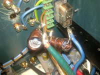
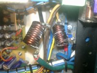
4) Finally, 0.72uH(11 turns on 11mm bit, 2mm copper wire, 2.2CM long)
Damping resistor parallel 15OHM
Now, everything feels like with 0.5uH, maybe even better, but clearly NOT WORSE Punchy bass region, more control over whole sound spectrum, feels like timing is just right now
Also, the inductors now are placed at speaker protection input terminals, there is no metals parts against them, also PCB is not induced with stray magnetic field.
Resistors are all 3W POWER METAL or Metal Oxide type located inside the inductor.
0.72uH :
Okey, finally got some results about different size of inductors impacting the sound on H-140 audio e-bay output.
First, as i mentioned:
1) ~0.5uH(16turns on 6mm drill, 1.4mm diameter of solid copper, 2.4CM long)
Damping resistor parallel 15OHM
Sound was different, amp was awaken from a sleep
And then:
2) ~1.9-2uH(21 turns on 10.5mm drill, d=1.5mm of wire, 3.1CM long)
Damping resistor parallel 10OHM
Completely lost the attack and punch, female vocals sounded maybe better... highs(hits, hats) rhythm had bad impact on... they were all there but in very lazy mood
Okey, here i have run out 1.4-1.5mm diameter copper wire, i had to use 2mm now.
3)~1.2 - 1.3uH(12 turns on 14.5mm bit, 2mm copper wire, 2.45CM long)
Damping resistor parallel 15OHM
Slowly comes back from the previous (2uH) inductor, rhythm is getting better here.
4) Finally, 0.72uH(11 turns on 11mm bit, 2mm copper wire, 2.2CM long)
Damping resistor parallel 15OHM
Now, everything feels like with 0.5uH, maybe even better, but clearly NOT WORSE
Punchy bass region, more control over whole sound spectrum, feels like timing is just right nowAlso, the inductors now are placed at speaker protection input terminals, there is no metals parts against them, also PCB is not induced with stray magnetic field.
Resistors are all 3W POWER METAL or Metal Oxide type located inside the inductor.
0.72uH :
Attachments
If you are interested 1R and no inductor is a choice. Don't be put off by damping factors or power loss. Some think this is the sound of valves and not the valves. The 1R will help the amplifier cope with back EMF better. I doubt you will like it. You might. In 1956 ( ish ) damping factors by measurement of > 3 were thought to work. The speakers were less floppy then. If your speakers are 4 R you will be at the limit.
Rensli - At 100-150R, there won't be a lot of damping of the coil resonance. Typical output coil dampers are 4.7-10R, give or take. However, I think you are introducing some unwanted band limiting with your higher resistance values, making a resonant rather than damped tank circuit and that will impact on the audio, probably as you describe.
You should not hear a loss of treble with normal LR values.
You should not hear a loss of treble with normal LR values.
Last edited:
Okey, finally got some results about different size of inductors impacting the sound on H-140 audio e-bay output.
First, as i mentioned:
1) ~0.5uH(16turns on 6mm drill, 1.4mm diameter of solid copper, 2.4CM long)
Damping resistor parallel 15OHM
Sound was different, amp was awaken from a sleep
And then:
2) ~1.9-2uH(21 turns on 10.5mm drill, d=1.5mm of wire, 3.1CM long)
Damping resistor parallel 10OHM
Completely lost the attack and punch, female vocals sounded maybe better... highs(hits, hats) rhythm had bad impact on... they were all there but in very lazy mood
Okey, here i have run out 1.4-1.5mm diameter copper wire, i had to use 2mm now.
3)~1.2 - 1.3uH(12 turns on 14.5mm bit, 2mm copper wire, 2.45CM long)
Damping resistor parallel 15OHM
Slowly comes back from the previous (2uH) inductor, rhythm is getting better here.
4) Finally, 0.72uH(11 turns on 11mm bit, 2mm copper wire, 2.2CM long)
Damping resistor parallel 15OHM
Now, everything feels like with 0.5uH, maybe even better, but clearly NOT WORSE
Also, the inductors now are placed at speaker protection input terminals, there is no metals parts against them, also PCB is not induced with stray magnetic field.
Resistors are all 3W POWER METAL or Metal Oxide type located inside the inductor.
0.72uH :
I do not have experience of using inductor to tune up the sound.
However, by looking at your experiment from different angle,
Using #1 as the reference point :
#2 experiment is having larger parasitic resistance. The Drill diameter is bigger thus longer wire and result in larger parasitic resistance
#3 experiment getting better since you start using 2mm wire. Total length is also shorter
#4 experiment is significantly shorter than #3, thus has lower parasitic effect . And better sound maybe ?
I do discover another simple tuning tip for H140 :
If you can reduce the resistance of those two 100 ohms emitter resister in the differential pair to 20 - 18 ohms, sound will be more transparent.
This is assuming that your differential pair transistor has good match thus not affecting the output DC value.
You can experiment by parallel 20 ohms to the original 100 ohms and see how it turns out. The mid range needs to to be fine tuned to properly accompany with high.
No, that's not how LR resonant circuits work. Resistance of the coil itself only affects current capacity and Q (the sharpness of the filter's response curve). The parallel resistance naturally affects the resonance frequency of the LR circuit but at such low values, it will also damp the resonance too. Try lower values than 10-15Ω with higher inductance like 1-2uH again and see...... there isnt much to damp, 2mm thick wire does that all for me anywayz...
That's why this hobby is so interesting
In my version of the amp with MJL3281 output transistors nothing sounds better than the 0.15 ohm metal element Ohmite resistor that I ended with. I strated at first with inductor/resistor combinations... My findings are somewhere in this, now quite big, thread.
In my version of the amp with MJL3281 output transistors nothing sounds better than the 0.15 ohm metal element Ohmite resistor that I ended with. I strated at first with inductor/resistor combinations... My findings are somewhere in this, now quite big, thread.
try setting the damping resistor to a value between 10% and 50% of the nominal output load value.No, that's not how LR resonant circuits work. Resistance of the coil itself only affects current capacity and Q (the sharpness of the filter's response curve). The parallel resistance naturally affects the resonance frequency of the LR circuit but at such low values, it will also damp the resonance too. Try lower values than 10-15Ω with higher inductance like 1-2uH again and see.
i.e. for 8ohms try values from 0r8 to 4r, not the 175% value that is 15r.
Yes, also got a little suspicious about 15R paralleling..., but is PSU bank damping counts here also ? That's the reason why i use high value resistors(10-15R) on output, atleast it is an idea to not over-damp the amp.
PSU configuration: 4700uF -> 2200uF -> Toroid coil(7uH) -> 4700uF -> 2200uF -> Toroid coil(~10uH) -> 4700uF -> 3x2200uF
Each toroid coil has 50mOHM resistance in parallel, totaling 100mOHM resistance per rail.
Or output damping has its own story and PSU damping is not related to it ?
Will try lower damping values as i get to diy in week or so.
Progress:
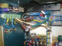
As i finished adjusting overheat protection, adding another ground wire from RCA signal GND inputs to PSU STAR GND(greater ground loop reduced to a smaller one by doing that) + 1nF ceramic suppression cap from RCA signal gnd to chassis, after that it was time to test the amp stability under high loads into 7.3ohm speakers
Cables are 1.7m long only and seems that 0.72uH is enaugh to keep these KIT's alive.
PSU configuration: 4700uF -> 2200uF -> Toroid coil(7uH) -> 4700uF -> 2200uF -> Toroid coil(~10uH) -> 4700uF -> 3x2200uF
Each toroid coil has 50mOHM resistance in parallel, totaling 100mOHM resistance per rail.
Or output damping has its own story and PSU damping is not related to it ?
Will try lower damping values as i get to diy in week or so.
Progress:
As i finished adjusting overheat protection, adding another ground wire from RCA signal GND inputs to PSU STAR GND(greater ground loop reduced to a smaller one by doing that) + 1nF ceramic suppression cap from RCA signal gnd to chassis, after that it was time to test the amp stability under high loads into 7.3ohm speakers
Cables are 1.7m long only and seems that 0.72uH is enaugh to keep these KIT's alive.
I think to buy Douglas Self's book would help. He goes to a lot of trouble to see how this works. He was a bit in the dark about it when starting to look at it. He found what is typical is almost a prescription !!! The exception I see is chip amps in T0220 5 pin like TDA2030. A Zobel of 100 nF 1R is seen without a choke. Often between bridged amps without going to ground.
This is more correct according to convention. The L-R network is designed to damp HF resonance with the speaker load, called "ringing". It should then, be designed around the typical load rather than just the amplifier. Good amplifier design texts cover this in detail.....Or output damping has its own story and PSU damping is not related to it....
- Home
- Amplifiers
- Solid State
- NAP-140 Clone Amp Kit on eBay