We did a debate about this on another thread and thought 130 mA was about the limit. The trick with biasing is to makes the problems happen at about 4 watts or at least 1 watt if you can. Someone might like to do the maths ( 177 mA ? 8 R ). Statistically this is a worse solution. That fails to take into account how we hear. With the Quad 303, 5 to 10 mA is the better choice. I have no idea if a 303 would work at 130 mA. I suspect it would. What is almost certain is 10 to 130 mA would be a worse choice.
Class A is often dissapointing. The power supply has to be much larger and to my ears favours classical music.
The JLH 10 watt amp is ideal for anyone wanting real class A. The better class A I have heard is SE valve about 5 to 8 watts. Don't fool yourself about power, it needs 10 times to really matter. 10 watts class A might not sound as powerful as 40 watts class AB. This might not be the 40 watts. It sometimes is that AB can sound better. This isn't distortion. It is that the power supply has reserves of power. Also hum should be lower for a given budget. 5 watts is about the average listening level regardless of system. When people have big houses they tend to have big speakers. The 5 watts always seems about right. Like an ultra powerful car the reserve power is nice to have.
Some time ago we discussed the original Naim transistors when the devices were to3 packages and used flying wires from PCB to the devices. These were BDY 56 and possibly ones of the same series. The other day I bought some modern devices that seem similar. Ironically Farnell retail ( CPC ) is much cheaper than Farnell trade. Very often true. My theory is the trade is often technicians who don't give a dam what the company pays.
MJ15015G - ON SEMICONDUCTOR - TRANSISTOR, NPN, TO-3 | CPC
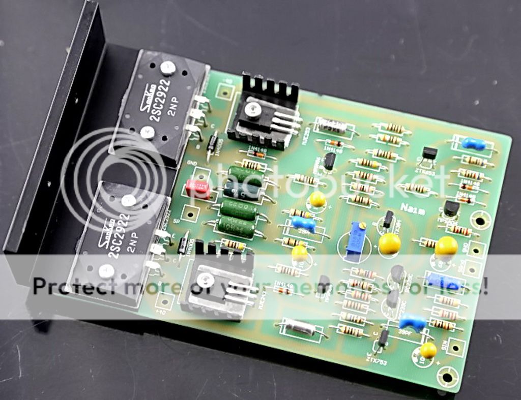
Finished front-end regulator PCB, the schematic of AVONDALE's the one you can find few pages back.
First i hooked the NAIM clones with the Laboratory supply (+/- 30V 5A) and the difference was already heard.
Then i played these with the 40V capacitor bank and 41V filter+regulator attached to naim.
I had a chance to test lots of combination's there with different HFE transistors, mainly BC550B and later a combination of BC550B and C.
To me it seems that the sound of naim and offset on the output is very dependable on these two transistors. With very wrong combinations, the offset can be as high as 100mV+ and never stabilize.
So there was the trouble...couldn't make them 0mV offset without changing this:

It is possible to balance them out to 0mV offset with the original 620ohm design if you are lucky and able to get right HFE transistors.
No luck for me... so i changed the value to 470ohm... and then i was able to simply stabilize them with BC550B HFE 425 in one position and BC550C HFE 595 in another position.
The Output offset is swinging between 0.0-1mV for now and is also stable at higher loads.
Question, if i put positive probe to the speaker output on naim board and negative to starground, what polarity dc offset should i read ? In this situation one board is having + 0.1mV and the other is having -0.1mV ! ? Does the dc offset polarity matters ?
I was suggested to try current mirror to eliminate the use of matching transistors in the pointed positions, will it ruin naim sound ?
First i hooked the NAIM clones with the Laboratory supply (+/- 30V 5A) and the difference was already heard.
Then i played these with the 40V capacitor bank and 41V filter+regulator attached to naim.
I had a chance to test lots of combination's there with different HFE transistors, mainly BC550B and later a combination of BC550B and C.
To me it seems that the sound of naim and offset on the output is very dependable on these two transistors. With very wrong combinations, the offset can be as high as 100mV+ and never stabilize.
So there was the trouble...couldn't make them 0mV offset without changing this:
It is possible to balance them out to 0mV offset with the original 620ohm design if you are lucky and able to get right HFE transistors.
No luck for me... so i changed the value to 470ohm... and then i was able to simply stabilize them with BC550B HFE 425 in one position and BC550C HFE 595 in another position.
The Output offset is swinging between 0.0-1mV for now and is also stable at higher loads.
Question, if i put positive probe to the speaker output on naim board and negative to starground, what polarity dc offset should i read ? In this situation one board is having + 0.1mV and the other is having -0.1mV ! ? Does the dc offset polarity matters ?
I was suggested to try current mirror to eliminate the use of matching transistors in the pointed positions, will it ruin naim sound ?
Attachments
It is normal in simple LTP input stages that Hfe and Vbe of the pair should be matched if you expect current balance and hence low offset at the output without testing...... Then i played these with the 40V capacitor bank and 41V filter+regulator attached to naim.
.....Does the dc offset polarity matters ?......I was suggested to try current mirror to eliminate the use of matching transistors in the pointed positions, will it ruin naim sound ?
The originally specified LTP pair are C category which is 420-800 Hfe by Fairchild's datasheet. Transistors with lower Hfe will require more serious adjustments to increase the current, as you found. Try using matched BC550C, whatever your meter reads. After all, many thousands of clones are produced as kits or complete/tested with acceptably low offset, regardless of the collector resistor imbalance.
If you look at the input stage circuit, you will see a gross imbalance (22k V 1.2k of the collector resistors) which forces a current imbalance and restores some 2nd harmonic distortion that would normally be cancelled by the LTP design. Changing this to a conventional design rather ruins the Naim sound and using a current mirror will likewise leave you with a standard Lin-Thompson design, the basis of a "blameless" amplifier and if you want clean, low THD audio, that's the simplest way to go but if you want original Naim sound, stick with the generic NAP/NCC200 design.
Perhaps you should restore the main rail supply to the input stage temporarily to investigate what is wrong there, since the original Naim design does work, without question.
Only our imagination or inappropriate speaker loads would require absolute DC balance, regardless of the suppositions and parroted opinions you see on other audio forums and websites. In fact, anywhere below +/- 50mV offset is fine with multiway speakers and this still applies to even up-market commercial Hifi products. Don't sweat this aspect because it will drift with temperature and time and below such a safe threshold, it's unimportant as is the polarity. For interest, the last time I measured the output offset on an original NAP140, it was -18/+35mV in my notes. It made no useful difference to get this any lower.
BTW, you appear to say that you are using regulated 41V rails with 40V caps. You should be using caps ≥10% higher rated voltage than the max. voltage applied, if the rating is what you refer to. Large cap. explosion is devastating, if not seriously injurious to anyone nearby.

Last edited:
BTW, you appear to say that you are using regulated 41V rails with 40V caps. You should be using caps ≥10% higher rated voltage than the max. voltage applied, if the rating is what you refer to. Large cap. explosion is devastating, if not seriously injurious to anyone nearby.
This is not true, these electrolytics are rated at 100V 85C atleast.
Everything else is also overrated, not under!!
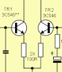
Rensil. The 22K and 1 K of the longtail pair input sets the sound ( dotted box ). First drawing is what to me would be the Naim sound.
The drawing No2 shows interesting mods. The BCV 62 is quite large and easy to use. I doubt you will ever build a better one out of hand selected parts. It's 20 V rating is OK as the VAS transistor that follows it clamps it at 0.7V. The Cdom ( 56 pF ) of the VAS should be increased to 100 pF at first as the amplifier will have more absolute gain. Back it off slowly and use test gear to be sure. That amplifer should now sound more like a Douglas Self design. BCV 61 is the NPN type if you have the need.
The bootstrap is a bit of fun. Some still prefer them. Although usually drawn with > 100 uF as a rule, 22 uf can work as the low frequency performance of the amp usually is good enough to cope below 1 kHz. 22 uF polyester 100 V type should be OK. My own tests show no awful distortion when 1 uF. Below that it is just possible to see it change. Some arrange the values differently. This version is easier to calculate. The current is 40 V / 4K = 10 mA as when 0.7V/68R of the original. 2 times 2K2 might be even closer. The bootstrap applies the same signal both sides of the resitors. As a result the reistor seem to raise it's value towards infinity. This is the perfect situation for a voltage amplifer as it seems to be fed from an infinitly high voltage without any danger that might bring. The reality is governed by gain. Bootsrap is because it is almost like by pulling on your bootstraps you could pull yourself into the air. You and I can not, it can! Bootsraps are returning so worth this little idea. One can bootstrap the input to raise it's impedance. This allows low noise without needing high driving current. If you want to use a passive preamp this is worth looking at. As long as gain does not exceed 95% it seems OK. This is the dreaded positive feedback. I would be uncertain over 95% as it seems to get ugly whilst not being dangerous. > 100 % is a no-no. On vave designs > 100% can happen without trying.
Ian Finch, nigel pearson, thanks for ideas and support (Y)
For a month or so after finishing amp's case and everything i will listen to it as it is (original) without current mirror and bootstrap.
As time go pass, i will mod them with the current mirror as a start and bootstrap as a finish. It would be easier then to tell the difference between the Naim and Douglas Self design.
The bootstrap VAS would be interesting if planning a new design. For your interest also this is approximately how an input bootstrap might look. It is a brave step to look at something like this. An oscilloscope and very cheap speaker if you do. How it works is that the LTP has to be balanced so as to work. Thus the < 100 % positive feedback can be had. The 1 K is a bit large so as to ensure it. The 22 uF is a bit small but should be OK. It allows low cost and high quality. A larger non polar cap could be used like 100 uF 100V. Non polars measure better if kept below 0.4V compared with polar types. That would be ideal for first watt principles ( what will 0.4 x 0.7 give as watts. > 7 watts so ideal if gain = 28 ). The bootstrapping must introduce some distortion (very small ). In practice the advantages might be worth the compromise. The input cap charging resistor can be made 200K. This will allow a 20 K volume control to nicely drive the amplifer. A CD player directly in should be loud enough. Not having a preamp can not only save money, it can sound better if the current demands are not too high. A phono stage should mimic a CD player. Typically voltage gain of 100 or 1000 MC. An old style tape deck or tuner might need a small boost. The 2 x 13 K maintain orignal DC balance well enough if I read 27K correctly. This will keep hiss the same also.
If you were to short the 22K of LTP ( 0R ) it would give almost correct Douglas Self style balance. 1K2 is to hint at what might be correct. Whilst it is unlikely the 56 pF VAS cap needs to be larger it would be prudent to assume 100 pF at first. One assumes 0.6V / 620 R = 1mA at the tail. Approximately the VAS is 0.6V and takes a small amount of current. 1K2 is about right to have a 50/50% split in the LTP.
One can remore the tail transistor and replace with a 39K 0.6 watt resistor. If the rails are regulated it might be better!!!!! Someone measured how well this works. The tail resistor verses the very best current source was about 90 dB verses 130 dB. Then it was found at > 50 kHz both about the same. As the LTP works in current mode the linearity is not greatly changed as the constant voltage causes a constant current when regulated voltage supplied. Some purists prefer a single tail resistor. For fun a PP3 batery and 9K1 resistor could be tried. 9 V is enough. If this were a voltage amp the near infinite resitance of a current source would be highly adventageous. It isn't so one must not assume the current source is best. The big surprise is the LTP resists noise better than anyone would think when the primitive type as when a resistor.
The emitter resistor of the VAS if the transistor current gain is 100 will give Z in at 100 x re, re is 25/10 mA = 2R5. Thus VAS Zin is circa 250 ohms. As the r LTP is 1K this is strict transconductance. In fact it isn't as that needs 240R ( 4 mA tail, not 1 mA ) or there abouts. If you measure the distortion from VAS collector this seems to have done no harm. If you measure the signal into the VAS base it looks very ugly, text books say unimportant. My own feeling is that the ugly signal is not just a ghost in the machine. If we add VAS 10R we now have true transconductance. At 22R we have a good result if this were a voltage amp. The VAS is best called a I to V converter or transimpedance stage.
If you do this VAS modification you you might notice this. Re ( external , re is inside the transistor ) 0R punchy with treble grit. Re = 22R , layered, sweet, less PRAT or punch.
The answer is a very high gain transisor. 2SB716C of the past at typical u= 400 would do the job. Even so 10 R might help. A high grade Darlington might be very good. I suspect the so called TID or slewing distortion is mostly this. As I to V is very typical of DAC's, it is worth learing how to do this. Could it be many DACs do the same? Even the RH ( RH84 ) series valve amps use a I to V convertor. I suspect valves do it rather well, that is against what one would think.
http://www.farnell.com/datasheets/1391103.pdf
If the Darlington was used it has 90 pF input capacitance. I dare say that might need investigating, I doubt it will be a problem. The advantage of all in one Darlington is it looks like the original device in having three terminals. I suspect other Darlingtons of lower current exist which do not compromise the needs so much. Ouput at 15 pF is not too bad. I suspect the Cdom could be reduced to 39pF.
If the original Naim resitor values used I feel sure it would be OK. D Self values about 2K4 and 0R. Corrected Naim ( not really required ) 2K4 and 47K ? Myself I would just try the transistor change as the the more interesting mod. The bootstraps are just to complete a 1970's state of the art review of how this amp could work.
If the original Naim resitor values used I feel sure it would be OK. D Self values about 2K4 and 0R. Corrected Naim ( not really required ) 2K4 and 47K ? Myself I would just try the transistor change as the the more interesting mod. The bootstraps are just to complete a 1970's state of the art review of how this amp could work.
Depends on the amplifier and the components that are used in there !In the original specification the power of the amplifier is from 30-40VDC. I am planning to use 42VDC due to only avaliable 2x29VAC transformer here. It will be ok?
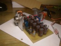
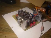
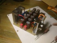
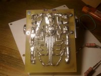
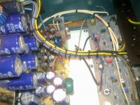
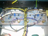
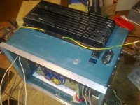
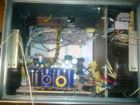
Half finished H-140 with the Avondale VBE from 51V DC regulated down to +/-41V DC, feeding Front End.
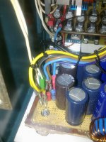
Outputs have they own PSU from OVER-SIZED capacitor bank +/-40V DC.
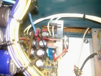
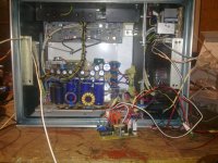
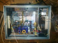
All GND-s are star-grounded to heavy ~10AWG copper wire beneath the PCB, hookup is seen on pictures.
All the wires are 18AWG taken from computer PSU...are these sufficient enaugh to deal with variable currents and not introduce side-effects to the sound ?
Decoupled the naim 2SC5200 outputs with 220uf 0.12OHM ESR capacitors, each cap has its own wire back to the STAR-GND.
Added output resistor instead of a COIL+Resistor Combination, used there 2x330mOHM 3W each in parallel to get desired ~170mOhm resistance on each speaker output. Will this ruin something in the sound ? Looked up the original naim schematics and they are using 0.22ohm there...will that resistor save the output transistors if shorted for a short period of time ? The temperature controlled on/off switch will be introduced as a last peace of work into this project.
About HUM, in fact, there is no such thing on the left channel, all i hear is nothing when i short input signal to ground. Right channel has something there (HUM), barely hearable, its probably caused by a speaker groundwire that was crossing the 500VA transformer.
Is there something wrong with the way the wire's are wired ? Don't have any good quality speakers yet... cant tell nothing in terms of sound.
This thing will be completely dismounted to ensure that EARTH to CHASSIS connection will last, i am still kinda skeptical about 18AWG wires, would it be pointless to use 16AWG instead ? .
Attachments
-
 190420151367.jpg432.4 KB · Views: 131
 -
 190420151366.jpg550.9 KB · Views: 116
 -
 190420151362.jpg587.3 KB · Views: 148
 -
 190420151361.jpg436.8 KB · Views: 161
 -
 190420151359.jpg463.7 KB · Views: 144
 -
 190420151357.jpg547.8 KB · Views: 164
 -
 190420151355.jpg509.3 KB · Views: 193
 -
 190420151353.jpg516.7 KB · Views: 203
Last edited:
Regarding of using computer 18 gauge wire, it is O.K. to reuse. But watch out for cheaper computer power supply using aluminum wire. They do not sound same as copper wire.
Yes they are copper (nickel or brass plated..
 ) but the copper is seen in each core if wire is cut in half(copper is visible from center of a core).. they are a little harder to solder too but that's not much of a problem.
BTW, is it worth grounding amp's STAR-Ground to the EARTH Chassis at the "Chassis STAR" where the mains and x-formers earth connection presents ? Last time when i have done that made things worse, from an oscilloscope there was some high AC spikes at amp's outputs
This could be heard even when attaching the Ear closely to a Speaker, barely but there was some high frequency signals in a completely random pattern....Re:
Try to use the same kind of wire to start with. nickel plating wire may have slight "thin" sound.
If you want to tune up the amp to your taste, you need to start with a natural sound to begin.
How big is the spike on the scope ?
Regarding the spike, there may be some oscillation. Improper wiring should not cause this issue. Unless you have cold soldering. Oscillation of course can be caused by grounding issue. But it is just one of the factor.
For experiment, have you try to increase the little 47pF - 100pF capacitor between Base and collector for the pre-driver stage ?
It may hurt the shape of square wave. However, that may be an indication of oscillation as well.
These are my second naim's from ebay, gave away the first kits, it had an unregulated filterbank for both FRONT-end and OUTPUT stage. Oscillated with 39pF capacitor. By listening to it, i had no idea of that oscillation at all Maybe one indication was there, the "high's" in music where sometimes very loudly presented
Yep, 100pf capacitor there removes the oscillation from the amp completely
If i remember correctly, they oscillated @ ~200Khz. Forgot the spike's amplitude when amp was grounded to mains EARTH...
With the oscillation they get warmer far faster then without and normalization after heavy load takes ages with oscillating amp. So, thermal runaway is guaranteed if poor cooling is used with these EBAY KITS!
I haven't checked this build for oscillation yet... but to me it seems they perform far better with separate FRONT-End and OUTPUT reg/caps. They tend to cool down faster, not so much heat also... everything is passive.
I have made some changes to the Zobel network in current EbayKits, from ebay the zobel was connected to signal ground on AMP PCB, then i cut the track to run the separate wire from ZOBEL to 0V STAR-GROUND. Also a separate front-end supply could simple stabilize the amp. Checking the amp with oscilloscope will be in future, if it also does that... at least the cure is known.
Maybe one indication was there, the "high's" in music where sometimes very loudly presented Yep, 100pf capacitor there removes the oscillation from the amp completely
If i remember correctly, they oscillated @ ~200Khz. Forgot the spike's amplitude when amp was grounded to mains EARTH...
With the oscillation they get warmer far faster then without and normalization after heavy load takes ages with oscillating amp. So, thermal runaway is guaranteed if poor cooling is used with these EBAY KITS!
I haven't checked this build for oscillation yet... but to me it seems they perform far better with separate FRONT-End and OUTPUT reg/caps. They tend to cool down faster, not so much heat also... everything is passive.
I have made some changes to the Zobel network in current EbayKits, from ebay the zobel was connected to signal ground on AMP PCB, then i cut the track to run the separate wire from ZOBEL to 0V STAR-GROUND. Also a separate front-end supply could simple stabilize the amp. Checking the amp with oscilloscope will be in future, if it also does that... at least the cure is known.
Last edited:
Re :
Congulation on your new working Amp.
Most of the DIY people stop here.
For me, one more step is the amp tunning, which may take month.
As you point out, using regulated power supply make the amp sound better.
1. One reason is the cleaness of the power supply.
2. 2nd reason is different de-coupling capacotor offer better sounding.
There are other things that you can do to improve the amp :
a. Double the current capacity (#14 solid wire as example) for the ground wire. This should clean up the high frequency.
b. For the regulated power supply de-coupling capacitor, try to increase or decrease the capacitance. Proper amount capacitance produce the best sound. Higher capacitance may color the sound more based on the capacitor sound signature. Lower capacitance will harden the bass. Adjust the amount of capacitance to your liking.
c. Adjust the idle current to the most sensitive threshold of 2SC5200 if that is what you are using. 32mA was the suggestion. However, the threshold varies by the temperature depending on your case ventilation.
d. I also add DC servo circuitry. By adjusting the OPA driver strength, it allows to adjust the width of center stage image. A little bit narrow center image allows better separation.
e. Or simply use the 47uF Tantalum capacitor as the feed back capacitor. It is not as good as DC servo but very simple to try.
f. Or do nothing. Just enjoy your new amp.
Re : Oscillation
One more thing :
Upon close inspection of your picture, you are using the kits from Aeon.
Same as me.
For that kits, I remove the front-end decoupling capacitor.
Make sure it does not oscillate again.
I really hate the sound of Nichicon FW 220uF capacitor.
First time when I listen, I was almost fainted. The sound is flat, no high, no low, just the mid range.
Cadalarm, i am pretty sure u can apply 42DC without changes to the amp boards. But to make sure google the component values that are directly attached to the +/- on the board(such as diodes, capacitors and transistors), that way u get to know more about your kits.
Thanks,
About these 220uf front-end decoupling caps, i haven't tried without them, but even with the first kit there was lots of Highs, warm middle and poor bass
With the new build and signal path input capacitor mods there is everything + more bass ( MODS: From the http://www.next.gr/uploads/47/power-amplifier-circuit-ncc200-Z-a.jpg)
About the bias: previous kits were set up @ 6-6.5mV across 2SC5200 emitter and output. It should be around 26-30mA of idle current. That was the point where going lower wouldn't make much difference and going further as someone suggested "38mA" flushed the sound imo. With these ebay H-140 audio kits, i wont suggest going more then 6mV with poor cooling. Also count the room temperature where the amp is IDLE-ing.
For proper biasing there is whole another technique witch needs PC, soundcard and so on to MAX out the sound.
.
Ventilation is questionable... running out from current capacity, ~ 80mA what is left from the amp soft start and temp control relay trigger PSU transformer.
There is no stop until everything is failsafe.
U means DC servo withopamp ? NE5534 and OPA2134 is what i have. Can i use Output's filter bank and regulate it down to suitable voltage for OPA's ? No room for noisy transformers in the case anymore....
Last edited:
Cadalarm,
If this is from China, watch out for fake Sankan transistor.
Fake transistors typically can not withstand the Vceo and Vcbo.
Meaning it may not survive at the speced VCC voltage.
Which power transistor to use will vary slightly in sound.
For example, I blew up 2SC5200 and simply replce it with TIP35C.
There is definally a sound difference between these transistors. So is the kind of wire and capacitor to use.
DC servo with opamp + high quality 0.1uF/0.22uF capacitor is intended to replace 47uF~100uF feed back capacitor.
Since OPA requires good power supply, it is better to pick up 42V AC and rectify again. If you tap off the +/- 42V DC, you will inherent the sound signature of that bulk capacitor. That capacitor is focus on huge capacitance, not sound quality.
I also removed the input capacitor, the sound become very transparent. This is assuming that your pre-amp output already has a DC blocking capacitor.
Why blocking DC twice ?
Regarding the thermal issue, I mount the bias transistor to the heat sink with a big washer and screw to hold it tight.
When heat sink is hot, Vce of the bias transistor reduced (bipolar transistor has positive temperature coefficient), thus reduce the 2.4V bias across TIP41, 42, 5200...
Changes i made:
Basically H-140 audio ebay kits are NCC200 clones, changed the front end input resistors from 330ohm(china schematic) to 220ohm(NCC200), they form a filter with 220uF electrolytes, kept the electrolytic's in place !
Re-wired amp with a ~14AWG copper wire i had laying around without isolation, had to dress them separately 14AWG for everything except signal and output decoupling caps.
Removed the output 170mOHM resistor, instead of this soldered a 16 turn 1.3mm wire coil with 15OHM resistor inside it !
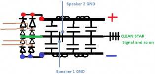
Finally, connected SPEAKER GND-s to the dirty STAR GND.
Turned The Thing on, WOW, sound is so much different, everything feels more separated, fine pleasure to the ears with crappy speakers
To me, good impact on the sound is behind the Inductor(Y)
Speaker dirty GND connection schematics:
Basically H-140 audio ebay kits are NCC200 clones, changed the front end input resistors from 330ohm(china schematic) to 220ohm(NCC200), they form a filter with 220uF electrolytes, kept the electrolytic's in place !
Re-wired amp with a ~14AWG copper wire i had laying around without isolation, had to dress them separately
14AWG for everything except signal and output decoupling caps.Removed the output 170mOHM resistor, instead of this soldered a 16 turn 1.3mm wire coil with 15OHM resistor inside it !
Finally, connected SPEAKER GND-s to the dirty STAR GND.
Turned The Thing on, WOW, sound is so much different, everything feels more separated, fine pleasure to the ears with crappy speakers
To me, good impact on the sound is behind the Inductor(Y)
Speaker dirty GND connection schematics:
Attachments
- Home
- Amplifiers
- Solid State
- NAP-140 Clone Amp Kit on eBay