LM317AHVT - FAIRCHILD SEMICONDUCTOR - IC, LDO VOLT REG, 57V, 1.5A, TO-220 | Farnell element14 UK
LM337TG - ON SEMICONDUCTOR - V REG ADJ -1.2/37V, TO-220-3, 337 | Farnell element14 UK
There is an OK version if Farnell are right.
What you can do is use a simple resistor divider and TIP3055 and 2955 for the other rail. It is a capacitance multiplier. My recent tests show it to be the better choice. Loose about 3 V to do a good job. Replace the divider lower arm with a zener diode if you prefer. As this is a thread seeking simplicity I will leave it at that. I suspect 470uF is a sensible filter capacitor for the lower arm. BD139/140 should be a slightly better choice. I choose 3055/2955 as they seem to have very low noise. I built a 450 V multiplier for a SE valve amp using a N FET. To say it worked well is to be too modest. I can not think how much money it saved over chokes which seems to be required devices in the religion of valves. On that amplifer it was say like running an enigine with or without an exhaust pipe. From memory - 60dB and - 86 dB related to 2.83 Vrms. It had an interesting effect, it mildly changed the distortion in a nice way. The Naim should not do that as it is not the power dumpers being regulated.
Shame on me Always trying to do it a hard way.
What an easy method using resistor divider, capacitance multiplier and just a VBE on the front end.
I surely will try them all, just to think threw how to make connection good and portable to change PSU components in no time.
A friend payed a visit with oscilloscope. NAIM H-140 was no surprise to him in therms of music and sound. Then we measured that the amp is oscillating. Changed the 56pf ceramic to a 100pf and the oscillation is gone.
Maybe it was that the A1145 Toshiba transistor wasn't fast enough because it may be a fake one. But the oscillation leads to another problem... if u set idle mV higher then 6mv, u may end up with FRIED outputs even at low listening level's IF your heat sink is not big enough.
This was with unregulated CCLCCLCCC configuration, one toroid for Stereo.
Also, why so many of u building mono-blocks ? I tested the crosstalk and yes, with a high volume, there is some signals on a muted speaker while the other channel is playing hard... but its so unnoticeable on low levels. Building mono's on separate chassis add something to the sound ? Dynamics maybe ?.. i doubt that.
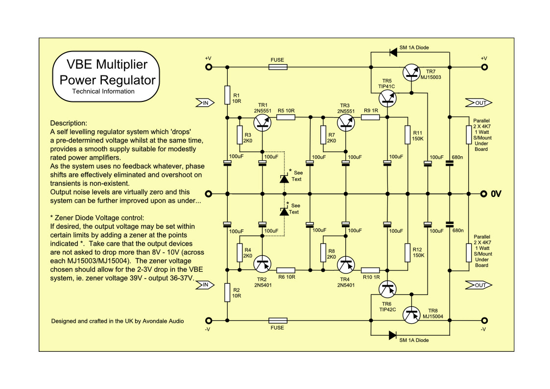
Found this one on Google : Easy to build, stable if adding zeners with opposite temperature coefficient's and this way it can be regulated easily to any output voltage. Also what important, that there is no feedback, which ensures stability problems ?
Always trying to do it a hard way.What an easy method using resistor divider, capacitance multiplier and just a VBE on the front end.
I surely will try them all, just to think threw how to make connection good and portable to change PSU components in no time.
A friend payed a visit with oscilloscope. NAIM H-140 was no surprise to him in therms of music and sound. Then we measured that the amp is oscillating. Changed the 56pf ceramic to a 100pf and the oscillation is gone.
Maybe it was that the A1145 Toshiba transistor wasn't fast enough because it may be a fake one. But the oscillation leads to another problem... if u set idle mV higher then 6mv, u may end up with FRIED outputs even at low listening level's IF your heat sink is not big enough.
This was with unregulated CCLCCLCCC configuration, one toroid for Stereo.
Also, why so many of u building mono-blocks ? I tested the crosstalk and yes, with a high volume, there is some signals on a muted speaker while the other channel is playing hard... but its so unnoticeable on low levels. Building mono's on separate chassis add something to the sound ? Dynamics maybe ?.. i doubt that.
Found this one on Google : Easy to build, stable if adding zeners with opposite temperature coefficient's and this way it can be regulated easily to any output voltage. Also what important, that there is no feedback, which ensures stability problems ?
H140 is a simplified schematic and PCB based on the generic early Naim amplifier schematic. Of course, none of the semis, caps etc are original and it seems you get a random selection of whatever parts are cheapest. It really doesn't have much in common with the original, or even with LJM's NAP140 clone.....H-140 was no surprise to him in therms of music and sound. Then we measured that the amp is oscillating. Changed the 56pf ceramic to a 100pf and the oscillation is gone.
There are many original features that result in sound quality difference such as the tantalum caps, VI limiters and transistor specs but the most obvious difference to hear is the compensation or Cdom cap and VAS transistor combo. as you found to be unstable in your kit.
Without ZTX653/753 with their 39 pF Cdom, you really have something else but more importantly, something not so good to my ears, at least. This is about the transistor Cob, Ccb etc. which varies with the signal voltage but you don't find many high Cob transistors that are also fairly fast like these. It's an interesting, counter-intuitive factor in sound quality.
Some would like to eliminate such distortion effects to get the lowest possible distortion performance but I tend to think that misses the point.
Try multiplier No1. It is all you need. Make a PNP version for the other rail.
Capacitance Multiplier Power Supply Filter
Capacitance Multiplier Power Supply Filter
 , Nigel
You too Ian and everyone.
All of this has made me want to make a better Quad 303. It and Naim are not very different. All I need is to take the power rails to 100 V or +/- 50 V. Another option is to use 4 x 303 clones in bridge. This includes the very exciting possibility of a single ended PSU with regulator. I would stick with 2N3055 if I did as the Quad has a very remarkable sound. The 303 has a very simple regulator. Sometimes this fails and reduces the amp power. One rare example failed high. This was theroretically way above 2N3055 maximums at >85 V. The sound difference was interesting. The high version more punchy and more dirty. NAP250 has a nice balance of the two. The multiplier is worth trying. It should make for a shiift towards NAP 250. If it looses 3 V so much the better. To have the VAS clip first is no bad thing. Nicer clipping. The thing to note with 303 was in devellopement circa 1965. No one to copy and yet advanced. I suspect Naim would be better with output triples as Quad and later Crimson.
Clone PCB's exist. Circa $20.
Quad 33 and Quad 303
I would not have put any Naim in the same "sound" class as a Quad 303.
In my head, Naims all seem to add something that is not in the input signal, i.e. the output of a Naim is not a scaled version of the input.
But in many systems they can sound good.
A loved a Naim driven active Linn system way back in the '80s
In my head, Naims all seem to add something that is not in the input signal, i.e. the output of a Naim is not a scaled version of the input.
But in many systems they can sound good.
A loved a Naim driven active Linn system way back in the '80s
Last edited:
That's a good point. It seems to come down to small details that many would never guess matter ( e.g. using your ears to set bandwidth ). Many months back a gentleman said his friend started Crimison after a visit to his house. His friend was not content just to hear Naim, he looked inside and said he could do better.
By coincidence my friend John Deans has one of the prototype Crimson amps. After that converstion I got the designer and him to get back in contact. One could say Crimson was born out of a Naim + 303 hybrid. Where Crimson departs is the higher slew rates. To be honest between John's Crown DC300 and the Crimson I prefer the DC300, it is so close to a 303. The Crimson seems gritty.
There are things to praise in the Crimson sound. My hunch is the NAP would be better if it's bandwidth and concept was with 303 / Crimson / Bryston output stage. The all use the all NPN dumpers. It is rumoured the NAP160 was seen first at Quad. This is strongly denied by the designer. The Quad ELS 57 was the reference speaker in it's design. The weird ( very weird ) thing is the sound differences between 303 and NAP 250 disolves when the 57's used. Very very odd. The Naim is better. That flat 2D sound stage of NAP 250 with snappy bass is nowhere to be heard. It just works. If you choose that have the PSU turned down. To be frank the 57/NAP250 is a very special combo. I would use an early DNM preamp if so. The DNW was made with the same objectives and will not harm the symbiosis. Garrard 401 or Lenco 75 to ice the cake.
You ought to open a new thread for all the products, comments and other matters you raise and leave dangling there Nigel. Some brands and products won't be recognized by many outside UK hifi industry and will deserve better detail and background but it's obvious that you have a strong interest and quite a bit to share from right across the spectrum of the British hi-fi industry as it was known.
Perhaps you could also define your understanding of "current dumpers" as opposed to any other amplifier output stage. Unless you mean an error-correcting type, similar to Quad's 405,306,606 etc. series or Technics' many adaptations of class S, that use of "current dumping" seems at odds with Walker & Albinson's paper.
Perhaps you could also define your understanding of "current dumpers" as opposed to any other amplifier output stage. Unless you mean an error-correcting type, similar to Quad's 405,306,606 etc. series or Technics' many adaptations of class S, that use of "current dumping" seems at odds with Walker & Albinson's paper.
I was hoping someone would. I only say these things because between being a Naim and not is a thin line. These kits will not really be at a guess more than 30% a real one. Even Naim proved this. Their amps sounded similar as moving up the range. This was strange as the circuit diagram was generic. All of these things are possible to the amature. And now the very bad news. Only your own ears can make the next move. This takes considerable learning. As luck would have it people like Ian , Andrew have great experiance. Ian more like me I suspect as someone who repaired and loved what he repaired. After years trends come out. A beautiful transformer usually gets my pulse rate up a bit in an amp.
There is a weird twist to this story. There is a guy who goes down the pub I have known for about 4 years. The other day we asked what he does? Repaires hi fi ! Funny world. Knowing this I get invited to a retailers meeting. These are the guys who sell washing machines and TV's. I loved every minute. Must be like a doctor going to a meeeting for Vets. The presenter was like Roger Moore and his age. Then he said " amongst us we have a manafacturer ". It was a golden moment. I got invited to all of their shops. One sadly has just closed. Richard has a 1940's TV in the shop. I wish I had the old 405 line recorders that one were in the stock rooom for him to use with it.
The nice thing about these Naim clone kits is they can be adapted. I have great doubts modern transitors of the 30 MHz plus type are the Naim sound. The Naim sound is a bit odd but gets better as you listen. It is rythmic, dry, 2D, gritty. What it does very well is make you like music. It is a battle of the head and the heart. The heart wins or should. There are better things out there. To my great surprise Hypex might be one. If you are not skillful at PSU design just buy their one. I am a bit angry with them as I suggested a mod that absolutly transforms them. That is to increase the gain to 400 mV. I suggested when the new PCB's made the header could be extended to allow a standard resistor to be used. If anyone wants to know that mod ask. I have mild Parkinsons symptoms so struggle to do this mod. To be clear this mod finds what Hypex didn't . They use the NE5532 in a way that is not ideal. The 5532 is not in the control loop and the extra gain is very useful. The circuit is set up in instramentation amp style. A single resistor in paralell sets the gain. The balanced input is great and is easy to use in standard single ended mode. If asking the sweet spot on NE5532 is gain of 10. Out of trendiness the op amp is now changed ( ? ). Rather a shame as 5532 used this way is one of the best. 400 mV is ideal to be drive form a pot directly . 10 K log would be OK.
I say about Hypex as I feel it would be less risky for people to build. It has a great sound.
Hello,
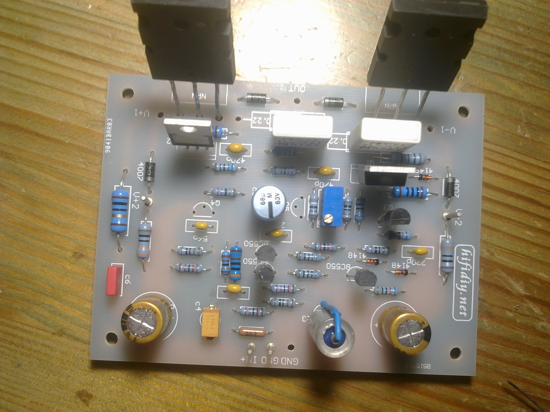
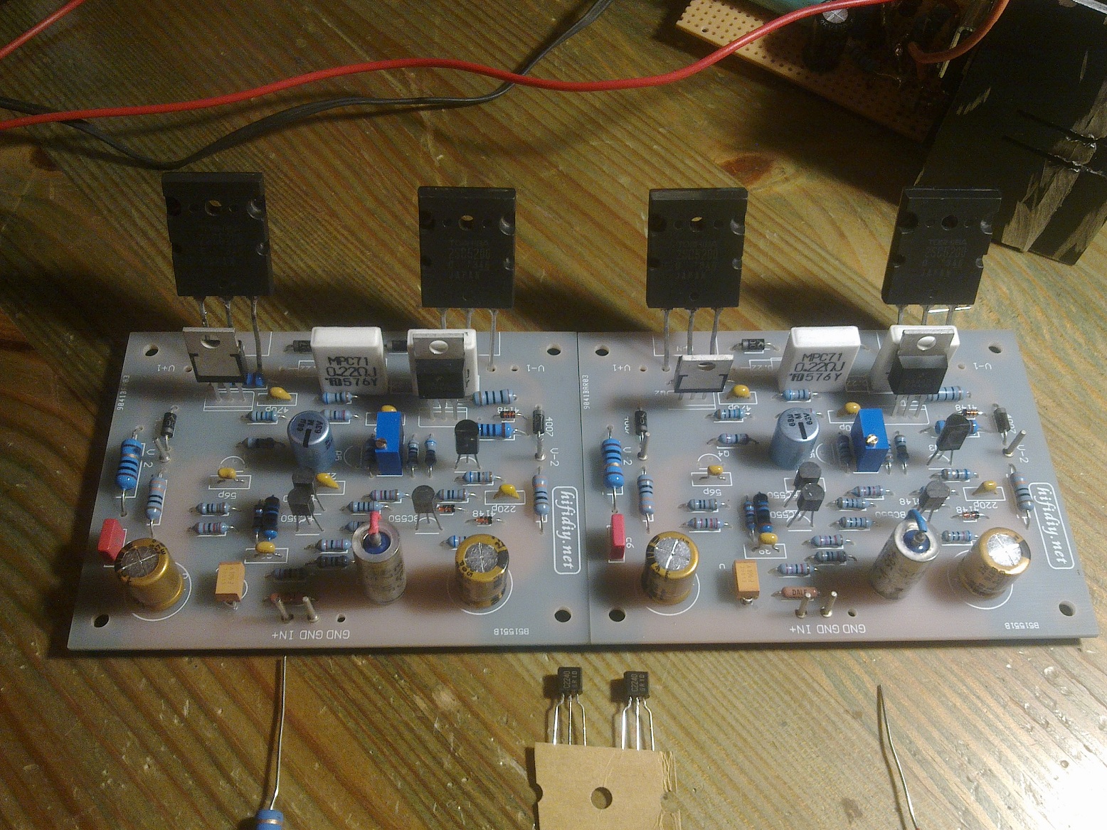
Finished the new boards today as all the components arrived.
500VA = 41VDC to the outputs
120VA = 53VDC + Cap multiplier board = 45VDC for the Front-end
Both boards share the same capacitor banks, transformers.
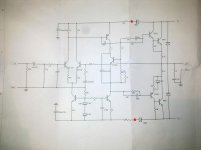
Can someone enlighten me what needs to be done to connect Cap. Multiplier board to the front end ? As i understand its parallel connection to the already existing 41VDC. Diodes on both sides prevent current going from FRONT END TO THE OUTPUT Transistors, resistors(330ohm) are there to clean the main 41VDC and probably stop high current flowing to front-end.
Do i need to remove anything or cut tracks ?
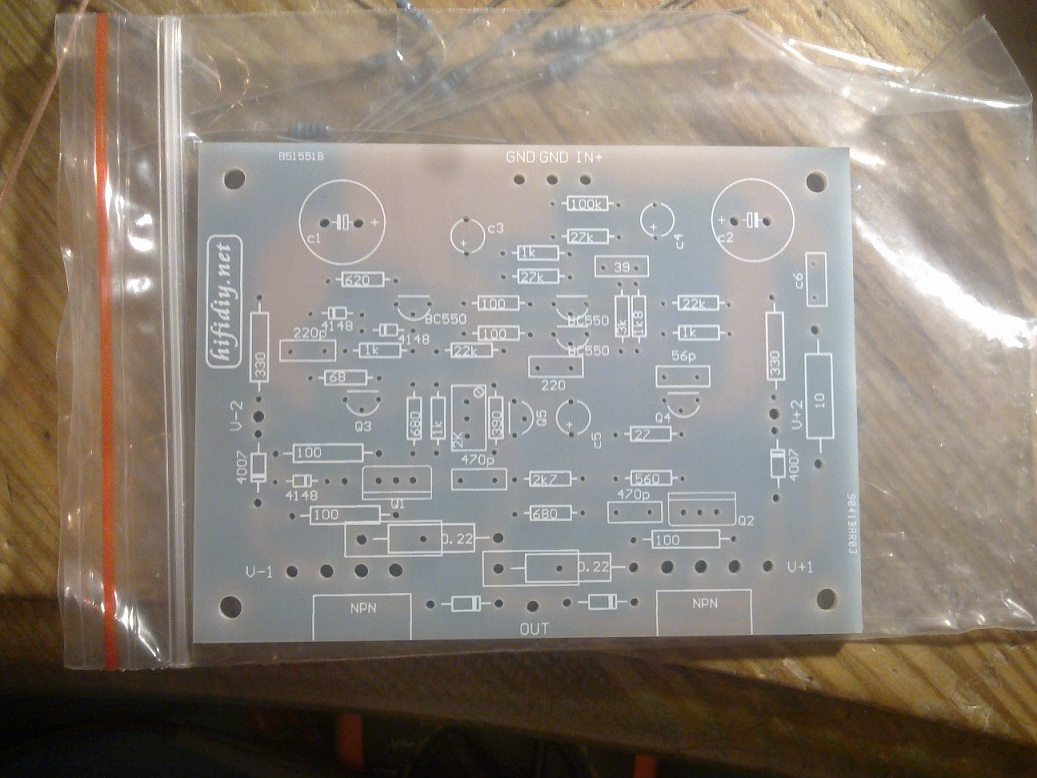
Some pics: Excuse me if some pics are too large.
Finished the new boards today as all the components arrived.
500VA = 41VDC to the outputs
120VA = 53VDC + Cap multiplier board = 45VDC for the Front-end
Both boards share the same capacitor banks, transformers.
Can someone enlighten me what needs to be done to connect Cap. Multiplier board to the front end ? As i understand its parallel connection to the already existing 41VDC. Diodes on both sides prevent current going from FRONT END TO THE OUTPUT Transistors, resistors(330ohm) are there to clean the main 41VDC and probably stop high current flowing to front-end.
Do i need to remove anything or cut tracks ?
Some pics: Excuse me if some pics are too large.
Your kits clearly have holes for 2 pairs of supply connector pins, V1+/- and V2+/-. I assume this allows both supplies to be connected independently, as you wish. I think the 4007 diodes normally connect these points for a single power supply, so you could remove those as they will be redundant.
There is surely a schematic for this, either at the hifidiy site, the seller's site or on other seller's sites. You might post that here, so others can be sure of what you have. You will need that to be certain or you could simply trace a circuit out from the PCB pattern.
There is surely a schematic for this, either at the hifidiy site, the seller's site or on other seller's sites. You might post that here, so others can be sure of what you have. You will need that to be certain or you could simply trace a circuit out from the PCB pattern.
Last edited:
removed and use a separate regulated supply
This one will be used.
There is a lot of wiring schematics between 0V separate PSU grounds
Is the new wiring schematic correct ?
Attachments
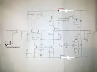
You are showing signal ground as the same point as your front end power supply ground. Only the input signal ground terminal should be connected there and then separately grounded to star ground. The power supply grounds (both main and front end) should also be returned separately to the power supply star ground - a slight but important distinction and the schematic does not show this.
Whilst it may be electrically similar, make certain the ground leads return independently to their ground points or your effort of adding cap. multiplier supplies will be wasted.
See Fig. 2 here, for the general connections for one or any number of separate power supplies for a typical amplifier: Power Supply Wiring Guidelines.
Last edited:
This schematic and board layout are different from naim / ncc 200 ground scheme.
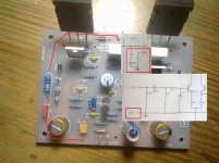
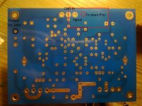
For example, these clones have their output 0V ground connected to the on-board ground plane First Pic from the left.
Second pic. shows real layout and the possible grounding of front-end to the clean (separate) PSU.
For example, these clones have their output 0V ground connected to the on-board ground plane
First Pic from the left.Second pic. shows real layout and the possible grounding of front-end to the clean (separate) PSU.
Attachments
The schematic is the same as that shown with some NAP140 clone kits too. It's just a circuit diagram and really doesn't show as much as it should for a kit. The PCB layout is certainly different but that does not necessarily mean better. There are now 2 star grounds and you must be careful which is used for the various power supply decoupling and smoothing caps, Zobel network, speaker ground return etc. I don't believe the Zobel network should be returned to ground at the input connection before being connected to power supply star ground in any case.This schematic and board layout are different from naim / ncc 200 ground scheme....
I suggest assembling and testing these as they are first, then adding the multipliers to be sure you have an improvement after fitting.
Having assembled a pair of these for a friend some years ago, I found there was a grounding problem which was a low level hum that was not present on other NAP140 clones but for the low price and intended use, it did not matter.
I haven't tried using a NAP140 in class A but this would not be simple or safe for any Quasi-complementary design like NAP140 that has such weak thermal coupling of the bias controller to the output stage.Has anybody tried to bias this amp about 1.5 or 2A per channel ? Is this safe only with heatsink modification ?
Probably, the bias controller circuit would best be modified to operate as a simple current regulator. This may not be so easy unless a suitable voltage reference is also used to keep the regulation stable in all ambient temperature conditions of use.
In any case, you will need large heatsinks, better than 0.4 deg./watt rating for each channel and reduced supply rails to 20-25V, depending on the actual transistor dissipation and SOA ratings. The driver transistors would benefit from larger, upright heatsinks too. It has been said many times that the supplied components are possibly fakes which may be fine for typical low power AB use but these would soon fail at high current.
I would not attempt this with a Quasi design unless you are prepared for some disasters. I can't imagine that the sound quality would be anything like the AB design either.
- Home
- Amplifiers
- Solid State
- NAP-140 Clone Amp Kit on eBay