You can solder some 10K 0.6 Watt resistors across the capacitor . The discharge rate is approximately 5CR . If 1000 uF that is 5 x 1000 x 10 000 / 1000 000 . That is slightly less than 1 minute . 4k7 would be OK and would do it is less than half the time . Power rating is VxV/R = 42 x 42 /4700 = < 0.4W . I have 10 K on my power amps to aid discharge . To discharge between 10 seconds to a minute is usually good practice .
In mains power suppression < 2 seconds is required in regulations ( e.g. the time for a child to remove a mains plug and touch the terminals ) . Douglas Self recommends 470 nF for a maximum value mains suppression capacitor . That would require a resistor of < 850 K > 0.1W . Ideally 2 x 390 K 2 W in series for voltage reasons mostly ( gives a 1000 V rating , 2 x 0.6 W gives 700 V typically which should be fine , the cap will protect the resistors a little so not as critical as when no capacitor ) . Not an area I would encourage for experiments , I only say because D S brings it up .
In mains power suppression < 2 seconds is required in regulations ( e.g. the time for a child to remove a mains plug and touch the terminals ) . Douglas Self recommends 470 nF for a maximum value mains suppression capacitor . That would require a resistor of < 850 K > 0.1W . Ideally 2 x 390 K 2 W in series for voltage reasons mostly ( gives a 1000 V rating , 2 x 0.6 W gives 700 V typically which should be fine , the cap will protect the resistors a little so not as critical as when no capacitor ) . Not an area I would encourage for experiments , I only say because D S brings it up .
Thank you for the tips.

Shouldn't something like that have been part of standard feature in every power supply? I'm somewhat disappointed that this one didn't come with it.You can solder some 10K 0.6 Watt resistors across the capacitor .
Shouldn't something like that have been part of standard feature in every power supply? I'm somewhat disappointed that this one didn't come with it.
It is standard option in the high voltage power supplies, as a safety measure. In our case, with the Naim, the caps will discharge pretty quick through the amplifier circuits because of the quiescent current. But, if the power supply is not an integral part of the amp, some higher value resistors added across the capacitors are good idea.
I've not seen any prebuilt or kit PSU assemblies for solid state audio amplifiers fitted with bleed resistors - on Ebay or elsewhere - ever!I'm somewhat disappointed that this one didn't come with it.
They aren't intended as freestanding power supply boards, but to remain connected to loads, amplifiers etc. where they will then discharge
as detailed by Ruwe. Once fitted to the amp, there's no problem or need for any resistor - just as there isn't in most commercial amplifiers.
I imagine you weren't aware of any such convention and that's probably half the annoyance.
I realized it soon after I posted above.I imagine you weren't aware of any such convention and that's probably half the annoyance.
Anyway, I finished assembling NAP 140 board, connected the power, heat sink and it works. I've read this thread from the beginning and the only check out info I found (I might have missed others) was about checking 0.22 ohm resistor voltage. Mine gets 4 mV DC. Where do I adjust to make it higher?
There is only one variable potentiometer. This is to adjust the bias (idling current). Note that the setting will vary because it is the air temperature in the amplifier that regulates the bias current. Closed up in a small case like the original amplifier, is fine, as after about 30 mins it stabilises and you get steady measurements. Out in the open air, it never stabilises and drifts about - sometimes dangerously.
For safety, I would keep the measurement to 5 mV across each resistor until it is enclosed in its case (measuring across both resistors for 10 mV is more accurate with typical DMMs) If you have the amplifier enclosed, you can quickly recheck after it has warmed up to operating condition and reset. Naim amplifiers are infamous for their sound quality improvement as they warm up.
Hope you enjoy and get to make some useful improvements on the basic kit. There's always something to learn and tinker with
If wanting to use cheap capacitors for valve amps the discharge resistor also makes certain the capacitors are equally changed . For example 1 bought 3 x 150 uF 200 V for about $1 recently ( Rapid Electronics UK clearance ) . I used 3 x 1M resistors ( one for each capacitor ) . This gives me 50 uF 600 V on a 480 V supply . This is to a capacitance multiplier . 1 M is about the optimum . 3 x 350 V resistors at 3 cents doing 3 vital jobs , equalizing charge , discharge and giving a bias current . As you can imagine if 480V it is useful to have it discharge . Equally if too aggressive the ripple voltages climb . Ripple is seldom a serious problem with transistor amps . With valve amps it is almost Malaria .
I recently had to build a laboratory standard mains voltage detector which I am proud to say came in at well below $1 ( US ) . It even works - 0.3 % at 100 C , -20 C 0 % ( 10 to 40 C required ) . It took me 10 minutes to conceive and 3 weeks to make easy to build ( I told my boss if a football match it went to penalties , he is very happy as the cost per unit is low , I had said $3 ) . My only problem was matching the discharge rate to the regulations and not screwing up the measurements .
I recently had to build a laboratory standard mains voltage detector which I am proud to say came in at well below $1 ( US ) . It even works - 0.3 % at 100 C , -20 C 0 % ( 10 to 40 C required ) . It took me 10 minutes to conceive and 3 weeks to make easy to build ( I told my boss if a football match it went to penalties , he is very happy as the cost per unit is low , I had said $3 ) . My only problem was matching the discharge rate to the regulations and not screwing up the measurements .
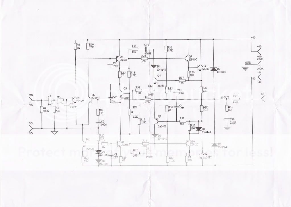
R17 on this image?There is only one variable potentiometer. This is to adjust the bias (idling current).
I tried to adjust mine but nothing changes. Could the trim pot be defective?
That's an unusual schematic - certainly has a lot of tweaks that aren't original or on other clones - not that they affect this problem.
A TIP41 for the Vbe multiplier? Now that's odd, since it doesn't have to be attached to anything like the heatsink.
If Q5 is reversed, C6 is faulty etc. there will be similar problems. It's worth checking Q5 pinouts on your meter,
since most now have a transistor Hfe test socket to verify transistor operation.
Have you bought/built 2 channels and compared relevant parts and operation?
It's from beginning part of this thread, not mine.That's an unusual schematic - certainly has a lot of tweaks that aren't original or on other clones - not that they affect this problem.
A TIP41 for the Vbe multiplier? Now that's odd, since it doesn't have to be attached to anything like the heatsink.
I read that the newer release has fixed the misprint on the board. I looked at the photo of one posted a year ago (http://www.diyaudio.com/forums/solid-state/112453-nap-140-clone-amp-kit-ebay-71.html#post2829419) and if his board worked the way it's assembled, I figured mine would too. Anyway, I'll check those to see if they are correct. Thanks.If Q5 is reversed, C6 is faulty etc. there will be similar problems. It's worth checking Q5 pinouts on your meter,
I only bought 1 as a test unit which will be for the center channel of my home theater. If it works out fine, then I would get a pair for my main speakers.Have you bought/built 2 channels and compared relevant parts and operation?
I just checked and R17 is fine. So it's something else I guess. Thanks.You can measure the voltage drop between Collecotr and Emitter of Q5.
If R17 is defective, Q5 Vce will not change.
Vbe multiplier transistor types
This is a rare opportunity to try almost anything! Any small audio NPN with Vceo> 30V and Icmax >250 mA should be ok.
e.g. BC546,7,8,9,550 MPSA06,42 2N5550,1. You should have no trouble as long as you get the appropriate pinout right.
Choose one with the EBC sequence, up or down, so that it fits easily if the PCB holes are also in a straight line.
Odd that BC546 was bad...
Last edited:
If the bias is changing it will show as a change in voltage across R29 or R30 . Rotel used to say 4.3 mV for the bias on their amps using the same resistor . It will be something in that region .Doubtless the instructions say something similar ? The way that this bias works makes it almost impossible that nothing is happening . When settled you might like to replace the bias pot with fixed resistors , it is ultra safe if no measuring errors occur . Some will say it sounds better that way . The argument is that the cermet used for adjustable resistors and the associated wiper is not ideal ( noise ) . I think if looking at the simplicity and the risks the fixed resistors version is better . Risk is getting it wrong , long term risk if the variable resistor fails ( and it will , espeailly if a tropical country ) . Set it and forget it if so .
I checked but it won't change no matter how many turns I make on trim pot. R29 stays at 2mV and R30 stays at 4mV.If the bias is changing it will show as a change in voltage across R29 or R30 .
Thanks for the tips on fixed resistor.
Just questions that have to asked to check measurements:
When powered,
First, is the meter set to low or autorange volts DC range and not some other range that appears to give readings?
1. Measure the voltage between the output connections. (have no other connections or input leads fitted)
There should be some DC voltage < 40mV typically.
2. Is Q5 replaced now and does the voltage across it (E-C) not vary when you adjust the pot?
3. Does the voltage across the pot (top to bottom on sch.) not vary when you adjust it? If voltages there
don't change, then remove the pot and test it out of circuit. Since the amplifier works, presumably
you must have tried audio satisfactorily with it, the output transistors must then be OK and correctly
installed so that leaves only Q5 and/or the pot. in doubt.
I'm following your posted schematic, which is different to your actual PCB and schematic so you'll need to cross-check.
4. Measure the voltage across R12 (68R) It should be ~0.4V for 6mA current through the VAS/bias generator circuit.
If the current is there, the previous checks must show voltages across Q5 and the pot. too.
At the output stage,
5. Measure between the emitter of Q11 and collector of Q12. This is the same as across both output "emitter" resistors.
It should be twice the required 5.5 mV for each resistor or 11 mV when the proper bias is set. Try adjusting again.
6. Measure Vbe (The voltage drop from base to emitter) for the output transistors and drivers (Q9-12).
It should be in the vicinity of 0.6V. Unless a solder joint has failed, the bias current must be there if the voltage
is being supplied by the bias circuit.
7. Is there a heatsink fitted and does it get even slightly warm after 10 mins or so?
Phew! Try these taking extra care not to slip with the probes, shorting the transistors and wrecking your good work!
Report back what you find plus any revelations or eureaks hopefully. Stay with it.
Last edited:
Did you mean R13 (680)? I don't see R12.4. Measure the voltage across R12 (68R) It should be ~0.4V for 6mA current through the VAS/bias generator circuit.
I'll go through those check points later today and report back. Thanks.
- Home
- Amplifiers
- Solid State
- NAP-140 Clone Amp Kit on eBay