Hello
How much total bias the amp use , I think you have to increase at least 50mA.
Can you measure it .Probably the bias is to low , when it rise a bit by the parts warm up the distortion & offset disappear .
Please check your bias connect a multi M between the power supp.and the + PC board .
Of course set up to measure mA . I think that can be the reason .
Also please check if the input G and the main ground connected . When I purchased the blue board (kit)I had some issue with the ground , I had no sound at all .
Greets
Hello
I just look up my schematics (I have three different type) all has the 22K .
I think you use use that resistor .
I also tested these schematic http://www.neilmcbride.co.uk/output-amp2.pdf, I didn't like the sound and has some issue with the bias set up . R15 must be 1k or 1.2K not 2K2 .With 2K2 I could not set up the bias well , only 7mA .
The input transistors 2SC2547E sound awful . BC546 or BC550 much better solution here .
More info here Neil McBride's HiFi Stuff
Greets
Last edited:
I'm troubleshooting what looks like the same ebay kit too. From what I glean from this insightful forum it seems like the different sellers of the hi-fi diy kit (NAP140-H) have been using various combinations of transistor substitutes with unpredictable results. On the board I'm working on now it's only stable at very low volume, turn it up and it triggers a fault condition. (Distorted output).
One interesting observation - I can only connect the load AFTER powering up the amp board or I immediately get -4V DC on the output. Any ideas why?
cheers!
Hi,
Apparently, these kits are the worst! ... My boards are different and they worked pretty much from the very beginning. Your problem is very weird and I don't know what's the cause. I suppose the differential pair doesn't start properly. The 0V at the output is depending on the differential pair match and balance. I hope you already added the missing resistor (22k) in the current source. Without it the current source transistor is not biased and all is a mess.
I had distortion with some types of driver transistors, which were inappropriate for some reason. I can only guess that they were loading too much or not enough the VAS stage.
I didn't use the transistors from the kit. My final version is using the following:
Diff. pair and current source 2SC2240
VAS stage ZTX753, ZTX653
Output current adjustment and drivers MJE243, MJE243
Power transistors MJL3281
I have 43pF in the VAS stage and the value of this capacitor is important, because it defines how the VAS stage will transfer the current difference from the diff. pair into voltage. Too low value - too much gain and oscillation. Too high - not enough gain (in reserve for the feedback), and distortion at high frequencies.
I guess the most important part in this amp is the combination between VAS transistor types, driver transistors types and this capacitor. May be I was just lucky, but the combination above is working.
By the way, the Avondale board (NCC200) has great reviews. I'm sure their transistor choice is very good.
Regards
Hello
How much total bias the amp use , I think you have to increase at least 50mA.
Can you measure it .Probably the bias is to low , when it rise a bit by the parts warm up the distortion & offset disappear .
Please check your bias connect a multi M between the power supp.and the + PC board .
Of course set up to measure mA . I think that can be the reason .
Also please check if the input G and the main ground connected . When I purchased the blue board (kit)I had some issue with the ground , I had no sound at all .
Greets
It's currently set to 25mA warmed up since I'm still troubleshooting it at this time. It plays well (no distortion, clean sound - no hum) only when the input signal is small (low volume). When I turn it up it suddently goes bad and even when I bring the level down again it doesn't make a difference anymore once it is triggered.
The ground/OV are connected on the board.
Thank you for your welcome suggestions and I'll be interested to know what changes you made to yours.
cheers!
Hi,
Apparently, these kits are the worst! ... My boards are different and they worked pretty much from the very beginning. Your problem is very weird and I don't know what's the cause. I suppose the differential pair doesn't start properly. The 0V at the output is depending on the differential pair match and balance.
I hope you already added the missing resistor (22k) in the current source. Without it the current source transistor is not biased and all is a mess.
I had distortion with some types of driver transistors, which were inappropriate for some reason. I can only guess that they were loading too much or not enough the VAS stage.
I didn't use the transistors from the kit. My final version is using the following:
Diff. pair and current source 2SC2240
VAS stage ZTX753, ZTX653
Output current adjustment and drivers MJE243, MJE243
Power transistors MJL3281
I have 43pF in the VAS stage and the value of this capacitor is important, because it defines how the VAS stage will transfer the current difference from the diff. pair into voltage. Too low value - too much gain and oscillation. Too high - not enough gain (in reserve for the feedback), and distortion at high frequencies.
I guess the most important part in this amp is the combination between VAS transistor types, driver transistors types and this capacitor. May be I was just lucky, but the combination above is working.
Regards
Your observations and suggestions seem to coincide with my suspicions with this kit. I got it to work with this wierd problem only after replacing the VAS stage with 2SA970 and 2SC2240 which I had lying around. I have on order the ZTX pair you mentioned and will be installing them over the weekend (or earlier, hopefully!).
Output drivers are currently MJE243, MJE253 (I think that's what you meant above)
")
Output stages are the provided 2SC5200
LTP is BC550 (provided in the kit) - will replace this if the VAS changes don't work. Then it'll be the power transistors next...
The 22k is in its proper place.
Thank you for sharing your experience and component substitutions.
cheers!
My transistors
LTP BC546B (BC550C has less bass and to much highs)
Tr3 MPSA06
VAS ZTX753 /653
Drivers MJE 15032/15033
Power transistors MJL3281A or better choice if you find 0281A .
I do not like the 2SC5200 for two reason , Toshiba stop production of these transistor more than 13 years .
To many knock of parts in the market .
I do not like sound wise also a bit to soft it has less control over the speaker .
The blue board I posted from Ebay and it sound great , it has unbelievable deep bass and nice top end .
I only have problem with the tube like sound mid section .To much distortion .
I want to improve that to .I believe is possible .
After the blue board I tested the Mc Bride schematic (please forget it )
Now I use the NCC200 schematic only difference I use flat package power transistors MJL0281A .
Soon I will test it and I will let you know how it sound .
Brainf
My advise to you for VAS 2SC970 /2SD2240 will be not the best choice .
Please use ZTX or like my blue board 2SB647 /2SD667 . Just pay attention because different pin out . The 2SB has thicker sound but not as clear as the ZTX .
My advise to you forget the silk screen on the board .
Take the schematic and build the amplifier after the schematics . I know it take a lot of time but in that case you will be sure all pars is in the right location .
I had problem with my blue board to .After I hock up it had no sound at all and I have very large offset .
I spent hours until I found out the Input ground was not connected to the main ground on the PC board also you can see the LTP transistors are reversed . To many mistake if you go after the silk screen .
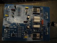
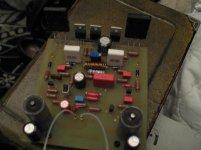
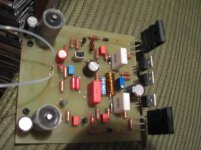
I post my old blue PC board and the new home made PC board which use the NCC200 schematics .
Greets
LTP BC546B (BC550C has less bass and to much highs)
Tr3 MPSA06
VAS ZTX753 /653
Drivers MJE 15032/15033
Power transistors MJL3281A or better choice if you find 0281A .
I do not like the 2SC5200 for two reason , Toshiba stop production of these transistor more than 13 years .
To many knock of parts in the market .
I do not like sound wise also a bit to soft it has less control over the speaker .
The blue board I posted from Ebay and it sound great , it has unbelievable deep bass and nice top end .
I only have problem with the tube like sound mid section .To much distortion .
I want to improve that to .I believe is possible .
After the blue board I tested the Mc Bride schematic (please forget it )
Now I use the NCC200 schematic only difference I use flat package power transistors MJL0281A .
Soon I will test it and I will let you know how it sound .
Brainf
My advise to you for VAS 2SC970 /2SD2240 will be not the best choice .
Please use ZTX or like my blue board 2SB647 /2SD667 . Just pay attention because different pin out . The 2SB has thicker sound but not as clear as the ZTX .
My advise to you forget the silk screen on the board .
Take the schematic and build the amplifier after the schematics . I know it take a lot of time but in that case you will be sure all pars is in the right location .
I had problem with my blue board to .After I hock up it had no sound at all and I have very large offset .
I spent hours until I found out the Input ground was not connected to the main ground on the PC board also you can see the LTP transistors are reversed . To many mistake if you go after the silk screen .
I post my old blue PC board and the new home made PC board which use the NCC200 schematics .
Greets
Attachments
Last edited:
Re: Brianf
Hi Brian,
You may be experiencing high frequency oscillation. When signal strong enough and reach output stage, a positive feedback could send the signal back to input and amplify again until reaching saturation point.
You can increase the capacitance (e.g. from 47pF to 100pF) of TR4 (the transistor tap off the differential pair output) see whether the issue resolved.
Watch out for the tweeter, oscillator can easily destroy the tweeter.
Hope this help
Lou
It's currently set to 25mA warmed up since I'm still troubleshooting it at this time. It plays well (no distortion, clean sound - no hum) only when the input signal is small (low volume). When I turn it up it suddently goes bad and even when I bring the level down again it doesn't make a difference anymore once it is triggered.
The ground/OV are connected on the board.
Thank you for your welcome suggestions and I'll be interested to know what changes you made to yours.
cheers!
Re: Vb and Vc of Q4 in the diagram
Look like the Q4 Vb and Vc values are switched.
This hould be a typo rather than wrong circuit.
Otherwise, the 27 ohm resistor will have more than 1A flow through and will smoke.
By the way, if you still have humming noise, try to disconect the ground from IEC ground and see what happened.
Look like the Q4 Vb and Vc values are switched.
This hould be a typo rather than wrong circuit.
Otherwise, the 27 ohm resistor will have more than 1A flow through and will smoke.
By the way, if you still have humming noise, try to disconect the ground from IEC ground and see what happened.
hope it can be useful
MUR860 8A rectifier diodes, 4 ohm speakers
Sorry to chime in, but I need advice on rectifier diodes.
I received my kit today, it's the blue from hifidiy.net.
My plan is to build a dual mono amp. I will use one 400VA 27v-27v transformer for both channels. Each channel will have a dual polarity PSU with peranders rectifier PCB, and since I have eight U860 diodes (8A, 600v) I figured I could use those. I will have 4 x 10.000uf filter caps per channel, 20.000uf between each rail and 0v.
My speakers are 4 ohm. Would I be OK with 8A diodes for the bridges, or should I get high current diodes, like MUR1620CT (16A)?
Thanks.
Jan
Last edited:
Hi,
can these nap clones sound as good as a class A amp like the mini-Aleph or Alephs? I've built the mini-A and AJ. If I build one of these, would I be stepping down dramatically in sound quality? is the sound closer to a gainclone?
How well can they drive 86dB speakers? I'm considering the gigaworks kits.
Would they be able to drive planars?
looking for less power consumption without too much loss in sound quality vs. class A.
thanks.
Re: 4 ohm speaker with 8A diode
Hi Jan,
The issue is not 4 ohm speaker, the issue is how much power you are planning to feed to your speaker for max volume listening.
NAP-140 means at 4 ohms load, each channel can only output 70W RMS with minimum distortion, so your should never try to send more than 4.18A RMS/5.9A peak to speaker (4.18A * 4.18A * 4 ohms = 70W)
Depending on the efficiency of your speaker, you will probably never use all 70W per channel during the listening. So it should be very safe in my opinion.
Even if you decide to pump 70W to your 4 ohm speaker all the time, the diode with 8A rating is more than the 5.9A peak current. You are still O.K.
Lou
Sorry to chime in, but I need advice on rectifier diodes.
I received my kit today, it's the blue from hifidiy.net.
My plan is to build a dual mono amp. I will use one 400VA 27v-27v transformer for both channels. Each channel will have a dual polarity PSU with peranders rectifier PCB, and since I have eight U860 diodes (8A, 600v) I figured I could use those. I will have 4 x 10.000uf filter caps per channel, 20.000uf between each rail and 0v.
My speakers are 4 ohm. Would I be OK with 8A diodes for the bridges, or should I get high current diodes, like MUR1620CT (16A)?
Thanks.
Jan
Brainf
My advise to you for VAS 2SC970 /2SD2240 will be not the best choice .
Please use ZTX or like my blue board 2SB647 /2SD667 . Just pay attention because different pin out . The 2SB has thicker sound but not as clear as the ZTX .
Yes I just received my ZTX pair and 2n5551 yesterday. Looking forward to the weekend to get them in and running.
Thank you for sharing your insights on the sound and your component choices. I will be trying them out!
cheers.
Hi Brian,
You may be experiencing high frequency oscillation. When signal strong enough and reach output stage, a positive feedback could send the signal back to input and amplify again until reaching saturation point.
You can increase the capacitance (e.g. from 47pF to 100pF) of TR4 (the transistor tap off the differential pair output) see whether the issue resolved.
Watch out for the tweeter, oscillator can easily destroy the tweeter.
Hope this help
Lou
Greetings Lou,
HF Oscillation is a real possibility - too bad I don't have a scope with me to confirm it. I'll try increasing it as suggested (it's currently 56pF).
I figure the ZTX i'll be substituting it with will help too as it has an inherently higher CoB then the kit supplied 2sa1145 (CoB = 2.5pF). I got it to work at low volume only after substituting it with 2SA970 (CoB=4pF). Not much differance but I think you're right (ZTX753 has a CoB of 30pF).
cheers!
In comparing the two circuits posted by Sangeet2 - the one in post #452 has an additional 22k resistor connecting the base of TR3 to Ground/OV.
Sangeet2... does your board have this?
Its not on the schematic, but on the board.
Look like the Q4 Vb and Vc values are switched.
This hould be a typo rather than wrong circuit.
Otherwise, the 27 ohm resistor will have more than 1A flow through and will smoke.
By the way, if you still have humming noise, try to disconect the ground from IEC ground and see what happened.
If I disconnect, I have not hum at all.
Re: Humming noise on NAP-140
One of the device in your house network may not wire correctly. e.g. TV, CD player ...
You can leave as is if you prefer no humming
I think Mr. Nelson Pass suggested using 10 ohm resistor from GND to IEC GND. I did not try it though. I just left it unconnected.
Don't forget attach Q5 to heat sink.
Lou
If I disconnect, I have not hum at all.
Re: Gainclone vs NAP140
Hi,
No one is commenting on your question. So I will put my 2 cents into it.
Sound quality is very subjective, the best way is for you to try it out yourself. It does not cost a lot to build, you can reuse most of the componet for your next project.
I do not have low efficiency nor low impedence speaker and can not comment on it.
Now for Gainclone vs NAP140 :
NAP140 can be build better than Gainclone or worse than Gainclone.
I have heard exactly the opposite comment from different source either praising NAP140 or hating NAP140.
So no matter what answer I give you, there is 50% chance that my answer is wrong.
Major reason is they did not tune the sound as manufacture did.
There are so many component in NAP140 can be tuned to your liking while Gainclone has limited capability.
They are mostly capacitors in the signal path :
1. 47uF/C6. Different brand and different voltage rating will alter the sound significantly. It cost little to replace as long as you have the patient.
2. Or you can remove C6 and replaced by DC Servo.
3. The pre-driver stage is powered through RC network (220 ohms and 100uF). By removing the diode and replacing RC with high quality power supply, sound will be improved. (need some $$)
4. If you look at the NCC2000 diagram, there is 2.2K and 47pF in parallel with 27K. These will also alter the sound.
5. I notice someone does not like 2SC5200. The right way to say it is 2SC5200 does not match well with other component in the circuitry. Depending on the issue, you can alter other componebt to match 2SC5200. e.g. The drive current flows through the huge decoupling capacitor, through 0.5 ohm, through 2SC5200 than through the speaker. You can parallel two 0.01uF metal film capacitor to each huge decoupling capacitor and tightening the bass (as example).
I tried option 1,2 and 5. I choose option 2 as the final selection.
Now you know it is very difficult to answer your question, right ?
Lou
Hi,
can these nap clones sound as good as a class A amp like the mini-Aleph or Alephs? I've built the mini-A and AJ. If I build one of these, would I be stepping down dramatically in sound quality? is the sound closer to a gainclone?
How well can they drive 86dB speakers? I'm considering the gigaworks kits.
Would they be able to drive planars?
looking for less power consumption without too much loss in sound quality vs. class A.
thanks.
Hi,
No one is commenting on your question. So I will put my 2 cents into it.
Sound quality is very subjective, the best way is for you to try it out yourself. It does not cost a lot to build, you can reuse most of the componet for your next project.
I do not have low efficiency nor low impedence speaker and can not comment on it.
Now for Gainclone vs NAP140 :
NAP140 can be build better than Gainclone or worse than Gainclone.
I have heard exactly the opposite comment from different source either praising NAP140 or hating NAP140.
So no matter what answer I give you, there is 50% chance that my answer is wrong.
Major reason is they did not tune the sound as manufacture did.
There are so many component in NAP140 can be tuned to your liking while Gainclone has limited capability.
They are mostly capacitors in the signal path :
1. 47uF/C6. Different brand and different voltage rating will alter the sound significantly. It cost little to replace as long as you have the patient.
2. Or you can remove C6 and replaced by DC Servo.
3. The pre-driver stage is powered through RC network (220 ohms and 100uF). By removing the diode and replacing RC with high quality power supply, sound will be improved. (need some $$)
4. If you look at the NCC2000 diagram, there is 2.2K and 47pF in parallel with 27K. These will also alter the sound.
5. I notice someone does not like 2SC5200. The right way to say it is 2SC5200 does not match well with other component in the circuitry. Depending on the issue, you can alter other componebt to match 2SC5200. e.g. The drive current flows through the huge decoupling capacitor, through 0.5 ohm, through 2SC5200 than through the speaker. You can parallel two 0.01uF metal film capacitor to each huge decoupling capacitor and tightening the bass (as example).
I tried option 1,2 and 5. I choose option 2 as the final selection.
Now you know it is very difficult to answer your question, right ?
Lou
Very good answer!
4. If you look at the NCC2000 diagram, there is 2.2K and 47pF in parallel with 27K. These will also alter the sound
Hello
What do you think if I leave out the 2.2K resistor with the 47pF capacitor that make the sound worst or better ?
I agree if we use separate power supp. for the pre-driver stage that would significantly would improve the sound .
Probably a good reg. power supp. it would be great .
I deed tested 3 verison NAP , all I can say it has incredible bass and nice top .
Also I have the P Daniel premium Gain clone kit , both amp great but I would prefer the Nap .Of course it depend on the parts U use .
Power supply etc.
Greets
- Home
- Amplifiers
- Solid State
- NAP-140 Clone Amp Kit on eBay