¿are the secondary wires of the toroidal correct? What is the exact model of this toroidal? Are the secondaries red-yellow-blue-green?
I guess so, cos i have the correct voltage: +/- 40 V
The point is that on these boards the input and output grounds are disconnected.
When you say "connected to the power components ground", I understand that you're talking about the output (speaker) ground.
No, i mean the ground from the Power supply...
Is the same problem on both channels?
Yes
Are you sure the resistors in the base of the differential pair are correct values? You should have 27k in the feedback path and something that gives you a sum of 27k on the input. I've seen combinations of (24k+2.7k) or (22k+4.7k).
Yes they have the right values
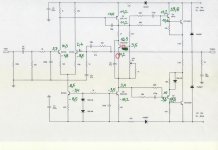
Please have a look on the attached schematic, i measured almost all Transistor voltages.
Attachments
Yes
Yes they have the right values
Please have a look on the attached schematic, i measured almost all Transistor voltages.
Very bad. Now try first the obvious in the following order:
1. With no power applied, check that the ground at the input is connected to the ground at C6. You have to measure 0 ohms between these points. If not, connect them with a wire.
2. Q4 is dead if I believe your measurement, but I don't. You can't have 39.8V supply and 11.2V at the emitter of Q4, because it will fry immediately the 330 ohms resistor. You have to measure everything with reference to ground or it doesn't help at all.
3. Check your power supplies after the 1N4007 diodes. Do you have 39V/-39V ?
3. BC550 in the current source may be gone too. Are you sure you measure -8.5V on both collector and emitter? ... If yes, it's gone.
More likely though the collector is to -1.8V. Please, re-check.
And again, if the emitter is at -8.5V, the other 330 ohms in the negative rail must be fried. Also 2x1N4148 should give you about -38.5V at the base of this transistor. It doesn't make any sense!
The Q1 must be with all voltages around negative! At least the 39.4V must be -39.4V
4. The differential pair voltages don't make sense.
-1.8V and -8.5V in practically the same point (the emitters)? If yes, both don't look like transistors anymore.
5. Not very important right now, but: change 27k on the input with 24k for better balance.
Very bad. Now try first the obvious in the following order:
I found out, that they delivered C560B instead BC550
I have a bunch of BC549 in my box, I think i should exchange them all and measure again. Will not do that before tomorrow...
1. With no power applied, check that the ground at the input is connected to the ground at C6. You have to measure 0 ohms between these points. If not, connect them with a wire.
I measure zero Ohm
2. Q4 is dead if I believe your measurement, but I don't. You can't have 39.8V supply and 11.2V at the emitter of Q4, because it will fry immediately the 330 ohms resistor. You have to measure everything with reference to ground or it doesn't help at all.
The 330 Ohms are both ok, all measuring are refering to ground, of course
3. Check your power supplies after the 1N4007 diodes. Do you have 39V/-39V ?
Yes
3. BC550 in the current source may be gone too. Are you sure you measure -8.5V on both collector and emitter? ... If yes, it's gone.
Looks like its gone then
More likely though the collector is to -1.8V. Please, re-check.
And again, if the emitter is at -8.5V, the other 330 ohms in the negative rail must be fried. Also 2x1N4148 should give you about -38.5V at the base of this transistor. It doesn't make any sense!
The Q1 must be with all voltages around negative! At least the 39.4V must be -39.4V
It is negative, I made mistake by drawing...sorry, but the other voltages are positive...
4. The differential pair voltages don't make sense.
-1.8V and -8.5V in practically the same point (the emitters)? If yes, both don't look like transistors anymore.
This is what i measured.
5. Not very important right now, but: change 27k on the input with 24k for better balance.
I will keep this in mind, thanks alot for your help
")
Not sure at the moment if I need to xchange other parts after xchanging all C560B
Not sure at the moment if I need to xchange other parts after xchanging all C560B
The drivers Q1, Q2 are the only that look OK. May be Q5 either. The rest is suspicious.
After you exchange practically all small transistors, measure again the voltages at the same points and attach the schematic again.
BC560 is completely different from BC550!!!
BC560 is PNP, and BC550 is NPN. So, yes, all is wrong if you use 560 instead of 550.
BC549 is NPN and will work, but there is a big chance to burn them again, because they are only 30V transistors. You better find BC550, BC547 or BC546, letter "B" or "C". "A"s gain is too low.
Good luck!
Ruwe, you're a Good Man! Sangeet, well, you're trying. And my boards haven't arrived. So I keep watching.... Sangeet hurry up so when my boards arrive I can have Ruwe for some troubleshooting...... any chance???
No transistor can sustain high reverse voltages. PNP replacing NPN types is very poor handling from China ...
I'll be here
... but if you are careful while placing and soldering the components, no troubleshooting is needed. This amp is very simple and trouble free. That's why it's impressive that it actually sounds so good...Is it really worth the truble to buy and build one? Will it compare to Nait 5 ?
This thread is way to long
Regards, L
Well, I don't know... Depends on how you build it, some small but important details in adjusting it, and in quality of some components, proper grounding scheme etc ...
Mine measures very well and sounds like a real Naim. I've heard Naim systems and mine sounds like one of them. I've never compared it side by side though. If you ask me would I buy NAP-150 for example, I'll say "no", because for the money difference I don't expect anything more... unless I can buy it for less than 500$... It would look nice next to the CD5i
Sangeet,
I had some time today to look again into your measurements.
The good news is that Q4 and Q3 are most likely OK.
I put them in the "suspicious" list, but I have the impression that they survived. Q4 is just turned on very hard.
If you replace the 3 small transistor at the input, you may have a working amp.
Ruwe, thanks for ur support.
Yes both amps are working now
After xchanging the small transistors the amp passes sound.
Today I will it put in the case.
Later I will post measurements from all transistors. I hope this will be helpful for some more people.
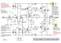
Please have a look at the attached schematic.
Is it necessary to match the transsitors?
What they mean by offset?
And what do you think leaving the 47pf and 2k2 off?
Yes both amps are working now
After xchanging the small transistors the amp passes sound.
Today I will it put in the case.
Later I will post measurements from all transistors. I hope this will be helpful for some more people.
Please have a look at the attached schematic.
Is it necessary to match the transsitors?
What they mean by offset?
And what do you think leaving the 47pf and 2k2 off?
Attachments
Last edited:
After everything is in the case:
DC Offset at the output is around 47mV
Trimmer is adjusted to 6mV at the output resistor.
No drift...
Amp is passing sound, but i have quiet a bit of hum which is very annoying
Strange, cos when the amps where not in the case it was quiet...
DC Offset at the output is around 47mV
Trimmer is adjusted to 6mV at the output resistor.
No drift...
Amp is passing sound, but i have quiet a bit of hum which is very annoying
Strange, cos when the amps where not in the case it was quiet...
hope it can be useful
Hi,
Congrats! It looks almost normal. The only disturbing thing is your current source. Something's not right there. The 2x1N4148 should give about -39.7V at the base of the transistor, if the supply is -41V. Now I see -36V which is too high and causes too much current to flow in the differential pair. These diodes may have gone bad. You have to check a little bit more in this area.
Your Q4 still looks on too hard, lets hope this will change when you repair the current source.
47mV is OK and it will improve when you correct the current source.
24kohms on the input is fine. Consider replacing the 56pF capacitor with something between 39pF and 47pF (best styroflex, or mica type).
I wouldn't worry about the RC circuit in the feedback. You can leave it as is, or experiment later.
About the transistor matching:
yours are very good if the whole batch is within 5%. For less DC output transistors have to be matched. In the same time, if the input one has about 10% higher hfe it will compensate for the base current going into the base of Q4... but because you have 100 ohms resistors in the emitters it won't matter very much anyway. I don't know how good is the idea to have these resistors though. The original circuit doesn't have them, and it doesn't have the 1N4007/330ohms in the power supply rail. They may affect the sound very much, but I have no idea for good or bad. If you find the amp to sound somewhat "dull" you can experiment by shorting all those on the board.
About the "enclosure effect": One possible reason can be that you RCA input cinches are not isolated from the enclosure. Do they have plastic washers? If yes, I don't know what may be the problem. Check what is changing in the ground connections when you move the whole thing into a box. I have few big posts on the previous pages and I think my grounding scheme is described there. I have nothing to add.
Regards
Hello
Soon I will test the schematic posted by Sangeet2 at 452 post .
I had the blue board from Ebay the sound not bad bat somehow it has high distortion in the mid range area .
Only you can realise the distortion if you com pare with a good amplifier .
Also I tried another verizon but not much improvement .
These schematic from NCC200 . I have the stuffed PC board I just need to hock up and test it .
I would like to hear some comment on the sound of your amp.
These is a great amp with deep bass , nice top but the tube like mind area unfortunately has lot of distortion .
Do any body have the same experience with these amp?
I will inform about the NCC200 as soon I tested .
I hope these time it will give more satisfaction .
Greets
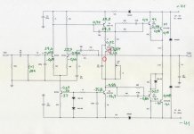
In comparing the two circuits posted by Sangeet2 - the one in post #452 has an additional 22k resistor connecting the base of TR3 to Ground/OV.
Sangeet2... does your board have this?
Hey, very nice observation. It's really missing on this schematic and it should be definitely there.
Hey, very nice observation. It's really missing on this schematic and it should be definitely there.
Thank you Ruwe.
I'm troubleshooting what looks like the same ebay kit too. From what I glean from this insightful forum it seems like the different sellers of the hi-fi diy kit (NAP140-H) have been using various combinations of transistor substitutes with unpredictable results. On the board I'm working on now it's only stable at very low volume, turn it up and it triggers a fault condition. (Distorted output).
One interesting observation - I can only connect the load AFTER powering up the amp board or I immediately get -4V DC on the output. Any ideas why?
cheers!
- Home
- Amplifiers
- Solid State
- NAP-140 Clone Amp Kit on eBay