Let me know if the quality is good enough, please.
An externally hosted image should be here but it was not working when we last tested it.
Are you sure you have measured the dc component correctly?
Component?
What u mean with that?
I have +/- 40 Volt from my power supply.
I can't see very well the resistors colours. I have 35V power supply, 25v toroidal. What about C1, it works ok? See the foto of my pcb, check all components:
Álbumes web de Picasa - julio cesar
Álbumes web de Picasa - julio cesar
Power should be fine fine also with 40 V.
C1 is put correctly on the board.
I put a better picture, have a look")
http://www.me.com/ro/djsangeet/Galleries/100080/Naim- --+/web.jpg?ver=12652079930001
C1 is put correctly on the board.
I put a better picture, have a look
http://www.me.com/ro/djsangeet/Galleries/100080/Naim- --+/web.jpg?ver=12652079930001
Ok,
After exchanging Q5,Q2 and Q1 I dont have smoke anymore.
I put the big Transistors 2SC5220 in. Put a Sine Signal in to the Input.
Connected an Old Speaker. I only get big Hum.
Disconnected the Speaker.
I measure at the Output of the Amp now about 10V DC!
Somebody can help me, please?
Sofar these kits are very disappointing, also they looked so cool in the beginning...
That is why I did not get these boards!. Too many problems. I read a lot about many problems that you have to deal with.There are other kits far better than this one.
Power should be fine fine also with 40 V.
C1 is put correctly on the board.
I put a better picture, have a look
http://www.me.com/ro/djsangeet/Galleries/100080/Naim- --+/web.jpg?ver=12652079930001
I can't open the link
Which ones? Did U build a working one?That is why I did not get these boards!. Too many problems. I read a lot about many problems that you have to deal with.There are other kits far better than this one.
Which ones? Did U build a working one?
*NAP-140.
*Nope, Luckily I chose for something else!.
Sorry...This should work now:
MobileMe Gallery
I think probably you have changed the transistor pins. This letters E and B next to Q5 refers to emitter and base? I think is wrong. Follow the E-C-B indications of this photo.
Attachments
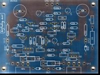
I think probably you have changed the transistor pins. This letters E and B next to Q5 refers to emitter and base? I think is wrong. Follow the E-C-B indications of this photo.
nono, i put in the transitor like indicated...if i would have messed with it, smoke would have come up again ;-)
I measure at the Output of the Amp now about 10V DC!
Are the input and the output grounds tied together?
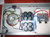
My Earth from IEC Socket goes to the screw which keeps the Transformer to the enclosure. From there a lead goes to the ground input of the power components.
Also the green and yellow leads from my transformer go to this screw.
From the output of the power components the other ground goes to the amp board.
It looks pretty similar then on your Amp.
I just put in the other amp board. There I am also measuring about 10 Dc V at the Output to the ground
At the moment no Input or Output sockets are connected...
Last edited:
Not sure if I understand you right...
But if i take an Ohm meter i have connection from chassis ground to the ground of the amp board. The green and yellow leads from my transformer also do have connection to chassis ground.
As stated before in 434, I did neither connect an input or output socket.
But if i take an Ohm meter i have connection from chassis ground to the ground of the amp board. The green and yellow leads from my transformer also do have connection to chassis ground.
As stated before in 434, I did neither connect an input or output socket.
My Earth from IEC Socket goes to the screw which keeps the Transformer to the enclosure. From there a lead goes to the ground input of the power components.
Also the green and yellow leads from my transformer go to this screw.
From the output of the power components the other ground goes to the amp board.
It looks pretty similar then on your Amp.
I just put in the other amp board. There I am also measuring about 10 Dc V at the Output to the ground
At the moment no Input or Output sockets are connected...
The point is that on these boards the input and output grounds are disconnected.
When you say "connected to the power components ground", I understand that you're talking about the output (speaker) ground.
Have you checked, as John65b suggests, the continuity between the input ground (where the input cable shield goes) and your "power components ground"? They must be connected.
I guess a picture is worth more then my english ;-)
¿are the secondary wires of the toroidal correct? What is the exact model of this toroidal? Are the secondaries red-yellow-blue-green?
I guess a picture is worth more then my english ;-)
These boards are different topology than mine. Why don't you attach the schematic so we can see the components numbers. It would help if you mark the DC voltages that you measure. Not only at the output but everywhere on the board.
Is the same problem on both channels?
I suspect that you may have a problem in the differential pair on the input. These are the transistors that maintain the 0V output (...assuming that your output transistors are OK)
Are you sure the resistors in the base of the differential pair are correct values? You should have 27k in the feedback path and something that gives you a sum of 27k on the input. I've seen combinations of (24k+2.7k) or (22k+4.7k).
- Home
- Amplifiers
- Solid State
- NAP-140 Clone Amp Kit on eBay