Quad 606,707,909 series amplifiers also use the idea successfully. The 2N3773 is a pretty tough customer and Ft is not a great concern there for current-dumping designs. There is a presumption in this 'safety in overkill' approach that you can't drive the amplifier beyond the SOA limits if it is capable of driving a short on the output with some standard type of input. It takes a lot of output device and relatively high series resistance to guarantee that it can do that repeatedly and recover with stability. Cumulative 2nd breakdown damage is another problem worth considering there.
I just don't see 2 pairs of typical medium SOA devices doing that job without the help of some extra resistance like large emitter resistor values, even light gauge wiring, fuses etc. - none being ideal. A design engineer would probably achieve safe operation on paper without difficulty but mere mortals would need a lot of expensive trials to know their protection would work as intended. That just isn't worth the effort or parts cost for me.
On the other hand, I've been building and listening to amplifiers with no protection other than rail fuses, for a very long time. That's how amplifiers were manufactured up to the mid 1970s when audio systems became universal home appliances and idiot-proofing became essential for Brand reputations. Even so, SOA (VI) limiters are not the issue that many would-be gurus of Naim design make out, or the company would have dropped this idea long ago.
In reality, the amplifier won't be used near the SOA protection locus in typical domestic applications with 8 ohm speakers. Much reported audio experience is really imagination, parroting and seeking respect by agreeing with peer opinion. It has been demonstrated here that real power is quite modest in most homes, with about 1-5W average and 10W peak output into typical domestic hi-fi speakers. Measure it for yourself and face the facts: http://www.diyaudio.com/forums/mult...much-voltage-power-do-your-speakers-need.html.
Some folk are paranoid about having enough clean power reserves for days that never come but they still want high power systems with vast, unused power reserves for imaginary requirements that could only involve driving 6" nails, Magneplanar speakers and neighbours insane. This misinformation about high domestic power requirements was part of a scare campaign begun in the late 1970s regarding the peak levels possible with existing LP vinyl technology. Perhaps JC is still concerned about that issue despite the shift to digital audio and defined max. signal levels more than 30 years ago
Last edited:
The thing most get wrong is the heatsink. Then there is the heat transfer washer. If the claims are to be believed they are half the problem. I have never completely trusted those figures. Some data seem to suggest one needs to double the heat sink if not using state of the art washers ( slight exageration ). I suspect the double size is the better route and use standard parts. I learnt this the hard way. Constant runing power supplies that take weeks to fail. All seems OK untill the transistor temperature inside the device is correctly estimated and found to be outside the SOA, albeit is slightly. The T03 metal can makes it far easier as the can top in some way represents the inside temperature, they also are at least as good as the best plastic types in shifting heat. There are many fake T03 devices. Sometimes they are better than the original as the can is ideal. That depends on how they are mounted. A T03 BD139 would be fun to try. The cheap 2N3055H has this as it's advantage if run at +/-34V max, in this is still shows the way. The H version is slightly less good sounding, it is tougher. I have doubts as I suspect few true 3055 exist today. For all we know a prefered type in a T03 can, MG15015 is even listed as that ( very nice and much like the BDY56 ). I usually take 60C amplifier case temperature if true Naim clone ( heatsink ) to be the limit. Naim set it higher at 75C with a thermal switch on the transistor mounting plate ( Micromark do them , 1/4 terminals as for toasters etc ). I have known the Naim fuse trip many times. I don't remember it caused any problems. My feeling is even a Naim NAP250 wouldn't be able to offer more than 40 continuous watts without the fuse tripping ( and only one channel ). That realates to 240 watts music. At that level distortion is obvious and would be into 4 ohms. Another mystery with Naim is how the heat gets from the plate to the case. It must be black body radiation mostly as the contact is via self tapping screws and perhaps the odd part that touches, it seems an ideal way NOT to do it. This was true of early examples.
The Ft of the Quad 606 transistors is even less than the worse quality 2N3055. Quad proved years ago that the Current Dumping amps do not need high speed transistors. This is because the amplifer is using feedforward correction with some feedback ( Read also Sandman amp and feedforward error correction ) . As long as the amplifer can give 50 kHz there is no distortion added by the Quad invention ( reality is different , not bad all the same ). It is suggested even the fastest pure feedback amplifiers will not put the Quad to shame. Similar arguements exist for the JLH 10 watt pure class A design. Because it is working in class A it has less high frequency correction to do. The measurements seem to meet the claim. The sound of the Quad is tight and slightly boring. This seems to be how it is protected rather than the Current Dumping. 606 went some way to proving that, 606 sounds to have more punch ( that's the thread back on track to mention it ). Quad for most of their history sold 70% power amps and 30 % preamps as a ratio, the surplus mostly sold as workhorse PA amps that must not fail. In fact a preamp was an idea so that professionals could use studio gear at home in lets say 1947 ( e.g. Leak, Quad, Hafler ). Quad was a household name in studios. Considered trustworthy and good enough to do domestic monitoring. Often sounding better than PA type amps. The HH-1200 was a PA device that could take on the Quad and win ( and beat the Naim to my mind ). The BBC used them as a universal amp. The MOSFET amps I like are inspired by the HH-1200. The HH replaced 2SA872C 2SB716C and 2SD756C of the Hitachi design for simple MPSA42 and 92. This allowed very high voltage rails and specs not unlike the Hitachi. HH also proved a 6mA VAS could drive a reliable 600 watts rms. The HH has no output drivers! I mention this as it would be assumed that without the 2SA/B/C devices all is lost, not so. I suspect the MPSA 92 had a folded heat sink as it is runing above book spec. The HH was sold in some numbers and past the BBC technical tests. As unlikely as it seems it would be a possible DIY design. I built one once on tag strip and had it work! I tried again and failed. I am almost 100% sure the NAP140 could not be built on tag strip.
I have always wondered what would happen if the Quad dumpers were forced to come on at a higher voltage. A simple diode in the base of the dumper might be enough. Make the class A work a bit harder. I suspect even 0.7V enough to matter. There always will be a switching point. Make it higher.
On second thoughts MPSA42 double VAS also needs a heatsink for this circuit above. Almost certain they did. The input pair don't. Note the very simple LTP. The Hitachi was even more so. The reason so many MOSFET's can be driven is the Cgs is bootstrapped to the speaker and not 0 volts. Cgd is the bigger problem. People forget a tweeter never needs 600 watts. Even so this amp would try to offer it. The fulll power bandwidth is possibly better than a Quad 606. The double VAS works as a constant voltage clamp. Seldom is the mismatch worse than 2% if slight care is taken on matching, it has a simple mirror of it's own, it's not really a CCS as it might seem altough that's debatable. The double voltage clamp ( 2 x 3K3, R23/24 ) is about as good as a current mirror although not offereing the raw current a mirror can. The slewing is quite good and symetrical. It is argued the Hitachi amp is less critical on slewing as the FET's are ultra fast when switching off, switching on is also fast. I have no data on these FET's for switch off, it could be a few nano seconds if typical. Pulse lasars use the FET switch off to get the speed they need, switch on is too slow. In class D amps this has been the way forward. The less time during switch off the less distortion, it's called dead time. If it is set badly the amplifer will kill itself. Class AB can do this ( Creek CAS 4040 did that when the transistor supplier " upgraded " the spec without saying, Not sure what that upgrade was, Mike was convinced. ) . FET's are thought to be unlikely to do this.
An awsome information: my Diy buddy friend have build blameless from the book.
He used Toshiba 2SC3281 2SA1302(green and black painted, old stock) on outputs, MJE350 series as drivers.
Sound was ok... but somehow not kicking.
Then he swapped those Toshibas for KT818GM and KT819GM series(3Mhz FT, Metal Cased, audio amplifier purpose).
Most interesting part is that he DID NOT reset the output bias.... From a first turn on.... it started playing and now he likes it....
So i am still tempted to try 2N3055 on naims when i receive my last PCB batch... These are not from Motorola either... they are from MEV company.. possibility is that they can handle Higher VCE and are maybe more rugged devices for SINGLE output-stage use.
The idea is to end up with 4 boards, NAP250 schematic original values, stereo with TOSHIBA outputs and the other pair with 2N3055 outputs. 2 identical Center-tapped transformer windings, 1 for each Stereo, unfortunately rail voltages will be +/-47V for each stereo units. For comparing, there will be No Front-End psu BS.
Its a matter of time when i get everything ready. VI limiter adjustment should be no problem anymore.
Last edited:
Use the MJ15015 ( not G as I said ) as it is the safer 2N3055.
http://www.onsemi.com/pub_link/Collateral/2N3055A-D.PDF
http://www.onsemi.com/pub_link/Collateral/2N3055A-D.PDF
Read about the genuine Hungarian MEV 2N3055 product offered on Ebay here: 2X 2N3055 100V 15A TO3 NPN Power Audio Transistor AF AMP KD503 Tested HFE 20 30 | eBay
These are rated at 100V Vceo so should not be problem with 40V rails but if you are going to use nominal 47V rails, alter the bias setting resistors again to get the LTP and VAS bias currents correct. You should know that ZTX parts for the VAS will also be on their limits at that voltage too - they're going to get quite hot.
These parts are allegedly >30 years old so they won't be shiny new. The marking and small insulation around the pins should be identical, otherwise you have the copycat $1 fakes and goodness knows what voltage/current limitations they will have.
MEV History
It costs moneyyyyUse the MJ15015 ( not G as I said ) as it is the safer 2N3055.
http://www.onsemi.com/pub_link/Collateral/2N3055A-D.PDF
At least i consider myself a lucky to receive those 2N3055 transistors.
Yes Ian Finch, i have the same markings(small blue circles around pins) and they are really tall compared to MJE15003 or 004 or even recently bought MJE2955(fake), it seems that Ebay transistors are "polished" to give a better shiny look.
Looking exactly same as in rod's elliot webpage.
I got these 4 transformers also for free. Inrush current is huge and i don't even know what type they are cuz they are covered fully with epox type material. (They are also mega silent)....
But connecting those transformers, i was able to get 35V-0-35V AC with using 2 blocks. The rest 2 transformer/blocks, they give the same result.
I will loose everything if i add resistance in power-rails... i have experimented this and i know sound will become worse.
I can't go lower on rail -voltage... i would love to make small heatsinks for T092 transistors and ZTX too to be on the safe side.
My input LPT is from BC182B(60V if i remember correctly), they are OLD and BIG compared to MPPSA06 for example, both are T092.
Last edited:
Ebay Chinese transistors are shiny new looking because they are new - just labelled at home yesterday by the supplier, to suit any TO3 type you like
I think you are looking at endless numbers of fakes and 2nd source manufactures in attempting to buy obsolete parts. MJ15015 is notorious for poor copies and fakes. Look at the variations here: Compare Prices on Mj15015 Transistor- Online Shopping/Buy Low Price Mj15015 Transistor at Factory Price | Aliexpress.com | Alibaba Group . Note the fake MEV brand referred to in the ESP article
At one time, when we needed to travel to Hong Kong to buy, it seemed many local suppliers and repairers had a bag full of MJ15015 in their parts bin and used them for power regulators when they failed in amplifiers. Why buy them? Because they were cheap and people find cheap irresistible, even when they have no clue what they are really buying. Stupid but true of people everywhere.
I am not sure this kit is the exact same as the one I used to make two old (one dead) NAP 90s into 140s. Neil James in the Bay Area (excellent resource for NAIM mods and repairs) used the cases and transformers from my old 90s and made two new amps which sound fantastic. They are playing now. I just got a Colorfly C4 DAP as a source for 24/192 FLAC files and the system has never sounded better.
Hi colinegreen,....Neil James in the Bay Area...used the cases and transformers from my old 90s and made two new amps which sound fantastic.....
There's isn't a lot of room in a NAP90 and the transformer is only 90VA to power both 30W amplifiers. Do you mean there is a single NAP140 clone in each case or are there 2 each in a larger NAP90/3 case? The transformer dictates the maximum power so it will be about the same 30W/8R as the NAP90.
Anyway, good that it turned out with such a pleasing result. Maybe you can talk Mr James into posting a few of his clone ideas and tips here too
An externally hosted image should be here but it was not working when we last tested it.
This was some years ago. I investigated more closely, and had not recalled that each of the NAP 90s is a mono block amp.
The system is active and has a SNAXO, one NAP 110 for the tweeters, and two mono NAP 90s with the chinese NAP 140 kit inside, for the woofers of IBLs.
The Colorfly C4 has been a revelation - the Source First thing has been proven.
Prior to this purchase, the LP12 was my source, and while it sounded good, it is not as good, I must admit. With 24bit/192khz we finally have enough resolution for digital.
I'll get Neil to put some Teddy Regs inside so it still counts as Flat Earth. I have read that replacing some capacitors inside the C4's analogue stage, via a Russian equivalent to this site.
suply voltage NAP200 too
I also wonder if we increase the odd 28v in NAP200 up to 30v or 32v (easy to find) what will happen?
I'm very frighten to barbecue, any idea?
I've got mine now, have found only one transformer 2x28v. is it ok to feed both channels from same lining?
thanks for all comments
I also wonder if we increase the odd 28v in NAP200 up to 30v or 32v (easy to find) what will happen?
I'm very frighten to barbecue, any idea?
I've got mine now, have found only one transformer 2x28v. is it ok to feed both channels from same lining?
thanks for all comments
With the specified components, you really need to have the supply voltages correct if you want the value in the NAP200 sound that you paid a lot more for. Otherwise, it's not much more than just another Naim clone with OK but probably not too special sound and some components running hotter than they should. The currents change too when voltage is increased. It can be a problem for parts ratings that likely run much closer, even above Vceo spec. values already.
However, local mains supplies vary from country to region, city etc. and you could be in a position to exploit this if, by some coincidence, the primary transformer voltage was truly 230V rated but your local supply was closer to 220V on average. Approximately, that would be 4% low and the secondary is 7% high so the 3% remaining difference is not unreasonable.
Using one power supply for both amplifiers kinda ruins the whole NAP200 dual-mono construction show. This really kills the project for me and wastes the care in the design of that PCB. Still, if you are more desperate about transformers than the amplifier, I guess you do what you can to get it working at least.
I plan to have one transformer wound along with some other types because local stocks may be cheap but they are shoddy imports and don't suit either, whilst local manufactured items are usually good custom builds but aren't prohibitively expensive, given that you get it right on both quality and precision.
@Atupi - I think you are talking about the same issue of higher supply voltages because its easier with common transformers/supplies. I don't have that sense of improvement with higher rail voltages but I have popped a few parts that way and some (expensive ZTX types) run quite a bit hotter and are close to their limits.
It's not hard to calculate the adjustments needed for TR3,6 emitter resistors to correct the bias of both LTP and VAS correctly. You only need about 7% increase though so I think it means using another E24 series part, maybe 680R and 75R in those cases but check the voltage drop across each before and after the change to be certain.
I think its not good to raise the supply rails with the recommended components but you aren't alone there. If you ever waded through the big NAP140 clone thread, you'd see the same issue was raised several times as it is with NCC200 variations.
Last edited:
Hello and Thanks!
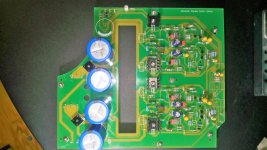
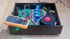
Hi, Just finished building a NAP200 Clone.
Many thanks to all here, it's all been valuable
Mind you with out a bit of luck and specific advice from Chris (Howarthcd), especially on the Toroid (Sourced from Tiger) and Algar_Emi (diagrams and part lists!!) I doubt I would be able to post some pics!
Lots of testing yet, but it plays music and appears (early days) to be running cool and best of all - no transformer noise - so far!
Anyway, I'm new to this, so very pleased to have got this far
Cheers
Robert
Attachments
Last edited:
That looks great Naimart and excellent work for someone new to DIY. Yep, the transformer looks the part and properly wound too. Did you buy the full kit or just the PCBs but parts of your own selection?
Now you'll have to look around for someone with an original or similar vintage model somewhere to have a listening comparison. That would make an interesting post too
Now you'll have to look around for someone with an original or similar vintage model somewhere to have a listening comparison. That would make an interesting post too
That looks great Naimart and excellent work for someone new to DIY. Yep, the transformer looks the part and properly wound too. Did you buy the full kit or just the PCBs but parts of your own selection?
Now you'll have to look around for someone with an original or similar vintage model somewhere to have a listening comparison. That would make an interesting post too
Thanks Ian.
I bought the PCB kit with loose parts
, and then the fun began! Initially just to see if I could, then it got a little more serious once I started to read on here! I've changed some of the Caowei supplied parts, the tantalums and the variable resistor (trim pot?) and I'm using some BC550C's in place of the supplied MSPA18 for TR1 and TR2.
Other than soldering, the biggest issue I had was with the case. Probably should have gone for the modusshop ones recommended here (and other sites) but was enticed by a A28 lite case from Ebay. I liked the idea that it had a lot of the cut-outs already done!
However I had various issues to overcome; main one was that the base was 1mm and too flexible for the 'Tiger'
. I had to add a 4mm aluminium base plate to strengthen it and give a better heatsink. The front facia is nice though and it had the switch cutout I wanted.When I get more confidence in it and it is off the 'light bulb limiter' I'll try it in my main system - maybe
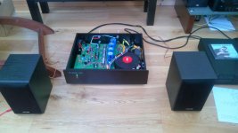
I connected it up with proper speaker cable and with better speakers, all fine and quiet - almost too quiet, if that makes sense - no hiss that I can hear. I'm using a passive preamp, so maybe that will come later!
Robert
Hi, Just finished building a NAP200 Clone.
Many thanks to all here, it's all been valuable
Mind you with out a bit of luck and specific advice from Chris (Howarthcd), especially on the Toroid (Sourced from Tiger) and Algar_Emi (diagrams and part lists!!) I doubt I would be able to post some pics!
Lots of testing yet, but it plays music and appears (early days) to be running cool and best of all - no transformer noise - so far!
Anyway, I'm new to this, so very pleased to have got this far
Cheers
Robert
Great looking build - you should be proud.
Out of curiosity I've just taken a quick look at the ebay listings for your case and it looks as though there are vents on the top. Apparently the NAP200 board is designed to be used in a sealed enclosure otherwise the amp can be subject to thermal runaway. I found a Chinese forum with posts relating to this kit and, with the help of Google Translate, found that this had actually happened to some kit-builders and with bad consequences. If your case has vents then you may wish to consider sealing them if you haven't already done so.
Chris
I hazard a guess that this what the top looks like, though there are a number of different 2U cases with that logo on the front panel. Two pieces of almost any flat sheet material could be neatly bonded to the underside of the top cover with a flexible, heat resistant glue such as Silastic 732. It only has to block airflow by covering the slots and not falling into the works.
An externally hosted image should be here but it was not working when we last tested it.
- Home
- Amplifiers
- Solid State
- NAP-140 Clone Amp Kit on eBay