So, about the mod that Elector suggested not needed?
Right, not needed. I think the suggestions are just for the IGTB version, which behaves a bit different than the HexFet version. However, all these suggestions are just made to keep the amp stable.
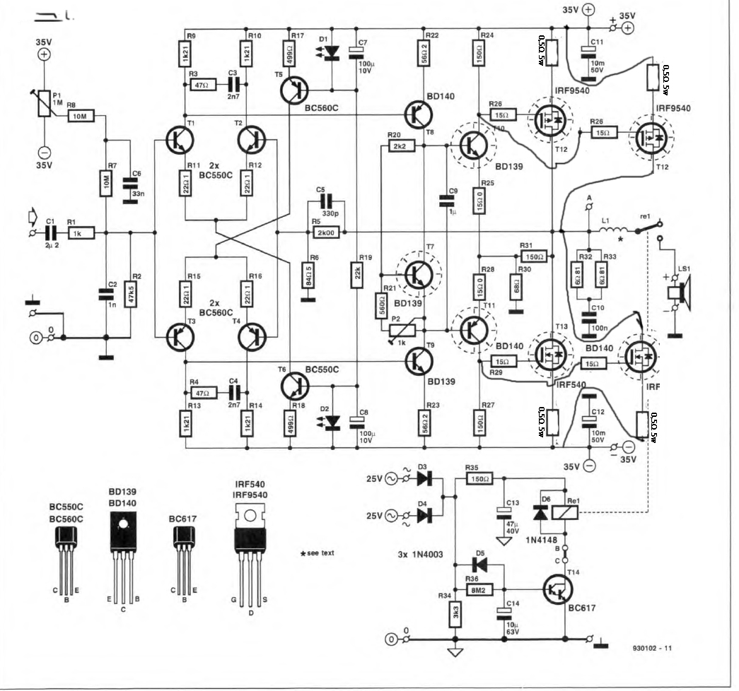
Btw, I use two of these amps for a subwoofer in bridge configuration. So I had to exchange the IRF540/9540 pair because they are just specified for 100V. The 220pF limits the slew-rate to about 9V/us. Keeping the spec value of 35V/us, one has to use 63pF instead, but I did not test the stability, yet.
Eddelarue,
When you take a look at R31 from your modded schematic and you compaire it with R21 from the original schematic isn't R31 placed wrong?
Hi meanman1964,
I used from this Mosfet output version
http://www.diyaudio.com/forums/solid-state/89526-diy-hexfet-amp-total-disaster.html
Than I'm right about R31?
Is your modded amp still working OK?
Long time ago I built this amplifier as a prototype and it worked very well. This prototype does not exist anymore with me.
regards
eD
Finally, I removed the 22nF and the amp keeps still stable, again important are just these two Miller caps to move the gain of the oscillation frequency <1. Hence, the 20k resistors “damage” the design principle of this type of amp.
All other components are kept the same as proposed by Elektor in its initial Hexfet 540/9540 version. Be sure you have equal! components as described in the Elektor article.
My comments to the other modes given in the thread vs. stability:
a.) Changing the “gate stoppers” to higher values does not help a lot, just slowing down the slew-rate
b.) Changing the current feed-back on (R25,R28) has just influence on the open loop gain, but not on the gain at the oscillation frequency.
c.) Changing the bias current of the input diff-pairs from 2mA to 4mA ok, will have positive effect on the Miller caps, but not necessary.
d.) Changing the band limiting network in the input diff pairs ok, will have positive effects on the gain at the oscillation frequency, but not necessary.
Can I also use this mod with the original hexfet 540/9540 or is it only for the IRFP240/9240 ?
I found the only place I needed a capacitor was on the VAS C to B on my IRFP240/9240.
I found a 220pf/100pf worked fine.
So did you also replaced the hexfet 540/9540 by the IRFP240/9240?
Did you add only the VAS cap or did the other mods as well?
hello everybody I need help with a modification I'd like to make. I have build Elektors project long time ago I had a problem with IRFxx N but with low bias current 50mAmp they work fine. Know I 'd like to to put hexfet in parallel My modification is the parallel hexfet but I'm not sure for the 0,5 Ohm source resistors I have to remove fuses or not. Of course I read all previous corrections and changes to make this amp with IRF9540N and 540N to get it work like gate resistors increase to 120 Ohm and R24 R27 to 100 or 120 and R25,R28 to 22Ohm
If some one did this parallel please tell me? my modification will work ?
If some one did this parallel please tell me? my modification will work ?
You asked this question here:
Compact Power Amplifier from Elektor
What have drawn is correct, each FET should retain its 0.5 ohm source resistor. Also the FET's should all ideally be from the same batch to ensure good tracking of bias current. In other words I would replace all the FET's with new.
I don't see any fuses on the diagram... just connect the FET's as you have drawn and it should be OK.
Thank you all I read all articles and the help I got was valuable. I did all corrections and modifications. I put I bias 30mA and dc offset around 0 with the trimers because I don't like to hear noise from loudspeaker
Now I am planning to give more power and change the transformer from 25Volts (34Dc) to 35Ac (49 DC) did any one try this ???
Now I am planning to give more power and change the transformer from 25Volts (34Dc) to 35Ac (49 DC) did any one try this ???
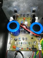
Attachments
There's definitely a big spread of gate voltages with FETs, so picking two random devices is probably going to result in one doing all the work. I'd carefully select matching devices even from a batch, drain current is a sensitive function of gate - source voltage.
Increasing the source resistor value will improve current sharing with less well matched devices, but reduces the output swing of course, as well as reducing transconductance.
Increasing the source resistor value will improve current sharing with less well matched devices, but reduces the output swing of course, as well as reducing transconductance.
BD139 and BD140 are rated at 80V, so that's a definite issue, the BC550/560 is 45V only, again a definite issue, and the FETs are right on the line at 100V rating.Now I am planning to give more power and change the transformer from 25Volts (34Dc) to 35Ac (49 DC) did any one try this ???
If some one did this parallel please tell me? my modification will work ?
I changed nothing except doubling the amount of fet's (and of course doubling of the gate and source resistors they each need).
The types used were International Rectifier. I had less (temperature)stable results with ST. The ceramic insulators worked best, don't use silicon if you can. Fet's were all of the same batch. I matched all transistors except the Fet's and didn't need an output relay when switching the amp on or off.
I think I ran around 100mA total, not less for sure.
It's been 25 years and then some ago..
Good luck!
Here are the articles from the UK magazine:
Elektor Electronics December 1993, Medium Power Hexfet Amplifier, Page 8, Link.
Elektor Electronics September 1995, Hexfet Amplifier Upgrade, Article 950077, Page 14, Link.
Elektor Electronics April 1995, Hexfet Amplifier Upgrade, Page 58, Link.
HEXFET Amplifier Upgrade September 1995 — 950077
Spurious oscillation may occur if power resistors are used which are different from the low-inductance ones specified in the article. The following component modifications should ensure stable operation of the amplifier:
– at the solder side of the board, fit a 27 nF capacitor in parallel with R31
– connect a 20 kΩ resistor between the collector of T8 and ground
– connect a 20 kΩ resistor between the collector of T9 and ground
– replace R20 by a 1.8 kΩ type
– replace R17 and R18 by 390 Ω types
– replace R3 and R4 by 33 Ω types
On our prototype (which did not suffer from oscillation), these modifications even produced better specifications.
- Status
- This old topic is closed. If you want to reopen this topic, contact a moderator using the "Report Post" button.
- Home
- Amplifiers
- Solid State
- HEXFET amp - please help me fix it.