burnedfingers said:I just found a Thaedra Head Amp schematic and a Thaedra II Head Amp schematic.
I have nothing on the power supply but that should be straight forward with a B+ of 22volts and B- of 22 volts.
Hi,
The supplies should be +/- 28vdc. There are two sets, one for the lineamp card and one for the two phono cards. There is also a muting relay circuit, which is highly suspect if you are getting nothing out of the main outs.
Hi Joe!
Regards, Mike.
d3imlay said:My problem is the relay isn't pulling in. I've got a signal to the relay. Power supplies seem to be OK although there are a couple scorched caps near the power resistors.
Hi,
Is the relay circuit on the motherboard or a plug in ? If the scorched caps are electrolytics they might be the cause (dried out). I have a relay circuit schematic I'll dig out but there was a number of attempts by GAS at this circuit so it might not be of use. I'll try to post it when I finish what I'm doing. Basically it's charging an electrolytic and pulling the relay. The power transistor is an MPSU07 and they used to fail. Check (obviously) the drop across the power resistor to see if the circuit is trying to pull the relay.
Mike.
Hi Joe,burnedfingers said:Mike,
I think they are on the main board if my memory is correct.
Actually both ways. GAS had enough trouble with the circuit that it made sense to make it a plug-in.
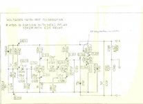
Here's the relay circuit. I'm surprized no one has this posted. Just a tidbit from the vault...
Enjoy, Mike.
Attachments
burnedfingers said:Thanks Mike,
I must have owned one of the early ones. Never ran across one with a plug in board. That would have been too easy.
Is it my imagination or could the circuit been made a little simpler yet?
I believe it was in the later iterations, this one was circa 1976 or so. I probably have a plug-in board, I was lazy though and just dug out the schematic I had.
Mike.
My version has the relay on the motherboard conveniently located under the power supply plug-in board so that you can't troubleshoot it.
Looking at the schematic that was posted, geez, what a complex circuit to do something so simple. I only saw one transistor on the board and a dropping resistor for the relay. I didn't follow the base drive circuit.
What does it take to pull the mother board out? The relay transistor is mounted so close to the board that you can't get to the pins.
d3imlay said:My version has the relay on the motherboard conveniently located under the power supply plug-in board so that you can't troubleshoot it.
Looking at the schematic that was posted, geez, what a complex circuit to do something so simple. I only saw one transistor on the board and a dropping resistor for the relay. I didn't follow the base drive circuit.
What does it take to pull the mother board out? The relay transistor is mounted so close to the board that you can't get to the pins.
It's been a while since I've looked at this, I'll pull the cover on my Theadra in the morning and maybe I can give you a few tips.
Mike.
d3imlay said:My version has the relay on the motherboard conveniently located under the power supply plug-in board so that you can't troubleshoot it.
What does it take to pull the mother board out? The relay transistor is mounted so close to the board that you can't get to the pins.
My version has the plug-in board. The bottom does come off so you can get to the circuit side while it's operating. The circuitry did not change much with time, my plug-in card is basically the same circuit as the schematic posted. It sounds like you know all of the obvious things to check.
At least you have a schematic.
Mike.
d3imlay said:I think my version is different because it doesn't appear to be very similar to the schematic that was posted. Also it appears that the bottom cover holds everything together which further impedes troubleshooting.
Hi,
There aren't that many variations so the only thing I can think is that you have a very early version. It might account for the simpler relay circuit. Are there version numbers silkscreened on the pcb's? 223,224 etc, no printing on the boards?
All of the Theadra's I'm familiar with have a structural support that connects the front and back panels allowing the the bottom cover to be removed while the motherboard is supported by the rear connectors and the controls up front with the chassis support pracket connecting the front panel to the transformer housing. Maybe yours was removed, although I can't think of why... The relay circuit I posted was an early version as well but GAS did have a bit of a rough edge with it's initial product releases that might account for this.
It's OK though, if you have a bit of patience we can work through this. Can you post any pictures?
Have you tested the power supplies for the +/- 28 volts? The relay circuit sits between the two supply and any imbalance might throw it off.
Can you describe the relay circuit, how many transistors, caps (electrolytics etc.) I have a dim recollection of something different and might have drawn a picture and filed it, it's been 30 years since.
A few checks might tell us what's working or not.
Regards, Mike.
Mike,
Your willingness to help is certainly appreciated. I'm tied up this week and can't look until Friday.
From what I can remember it looks like there was only 1 transistor near the relay. There's a dropping resistor near the relay that I theink connect to teh coil.
I was not very comfortable pulling the bottom panel with only the connectors securing the rear panel. I did see the support from front to rear, but the xfmr looks pretty heavy. I'll get another look this weekend.
The S/N for mine, I think, is 500359.
d3imlay said:Mike,
Your willingness to help is certainly appreciated. I'm tied up this week and can't look until Friday.
From what I can remember it looks like there was only 1 transistor near the relay. There's a dropping resistor near the relay that I theink connect to teh coil.
I was not very comfortable pulling the bottom panel with only the connectors securing the rear panel. I did see the support from front to rear, but the xfmr looks pretty heavy. I'll get another look this weekend.
The S/N for mine, I think, is 500359.
No problem, I'm not going anywhere.
I don't think you will find the chassis a flimsy as you think, but you can leave the top cover attached with a couple screws front/back while you have the bottom off. Start by looking for the obvious stuff like solder joints with hairline cracks and overheated connections. I've solved many problems this way so it's usually a good place for me to start.
Give me a holler if you have a question, it's ancient history now but I've worked on hundreds of them in a past life. They tell me it's like riding a bicycle.
Regards, Mike.
- Status
- This old topic is closed. If you want to reopen this topic, contact a moderator using the "Report Post" button.
- Home
- Amplifiers
- Solid State
- GAS Thaedra