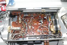
I purchased a Rotel RX-400 receiver - when I plug it in, nothing happens, no lights, no output. So, I lifted the covers and started poking around with my DMM. What I have found so far :
(a) The power cord is fine because the 120 VAC is coming through into the power supply
(b) The transformer looks OK because I measured the output and found it in the range of 12 VAC. I am assuming this is OK.
Now, I am stuck - I have no idea what to look at next. The AC fuses are fine (measured the resistance across each of them and they are not open).
I have the schematic that I am happy to email to anyone who volunteers to help me understand what items to test next
Thanks
For sure you will have a lot of folks helping you...but,
if you try to motivate us will be easier.
Post the schematic, or better, the power part of the schematic...post images, pictures from the amplifier/equipment insides.
Doing that will be easier, as you will atract more people because of the pictures, because of the schematics and because your friendly behavior.
We are fanatics, that kind of guys that cannot watch an amplifier alike normal people...we want to open, to inspect inside...so...give us this kind gift that will produce for you a nice image and will result in fast return related the things you ask for.
I cannot speak in the place of others...but in my perception, the way you entered is:
Do for me
Help me
Teach me
And that will provide schematic (the gift for us) to the one will help you.... can be made in better way..reason why my suggestion to you
and you gave not "food for fanatics"....no picture, no detail.... you know...honey for bees...bond for dogs...those things.
Here is my suggestion to you.... give some...you will receive enormous return.
Images can be jpeg, gif, pdf files and many others you will see during the attachment the instructions...limit is 1000 by 1000 pixels of data and cannot be bigger than 100K
regards,
Carlos
I'll probably revive this thread a bit. My cousin has this model and it stopped working. So I've opened it up now and looks like it definitely needs all electrolytic caps replaced.
I made some mods to it when he and I were both young dudes. Awful job, IMO! It was probably a mod that took out the light and meters. I think the amp portion of the circuit is fine. But I will report back on my actual results.
I made some mods to it when he and I were both young dudes. Awful job, IMO!
It was probably a mod that took out the light and meters. I think the amp portion of the circuit is fine. But I will report back on my actual results.I'll definitely supply some links and pics here. I was googling for info on the receiver and found this old thread.
Receiver manual is circa 1980, so probably bears lots of traits of '70s.
My cousin has put me on the spot to get this running as his parents are celebrating their 50th at the end of the month and he wants the receiver to use at the small gathering to supply music.
I just thought it would be a good idea to update this thread in case someone has one or runs into one and would like to restore it.
Sounds good. I would have a backup amp just in case this one can't be brought back to life.
I 'repaired' my mother and father inlaw's Teac Costco home theater amp earlier this spring.
The output transistors were failing and causing the amp to think it was overheating -- thus
putting it into protect mode. I pulled all components in the amp section, tapped off the
headphone IC and ran that into my working Rotel amp. Works great as a preamp only and
the inlaws don't need to learn a new remote control. The switched AC turns on the Rotel amp.
Some fixes are beyond me, but there is always another bailing wire and duct tape fix-it.
(insert banjo music here)
gni -
Yes, his brother has a system he can use, but I actually finished the cap replacement this weekend and no smoke. What a relief!
But the left channel kept cutting out and then disappeared altogether. I traced it down to the litz wire I used to run to the speaker output terminals from the output transistors. At the time I did the mods, I had a Radio Shack pencil iron and I had to solder the connections to those copper Edison posts. The problem is cold/weak solder joints and with litz wire, to boot!
Our local computer store carries Caig Labs cleaner for carbon pots so this receiver should be ready for prime time by end of this week!
My cousin didn't like the little spring clips at the back for attaching the speaker wire. I removed the panel of clips and cut out some plexiglas to mount Edison Price Music posts.
I removed all the original speaker wire and replaced it with Litz wire. IIRC, Cardas.
I also couldn't find filter caps to replace the originals (4700 uF 25V caps). So I made a small pc board to accept 6800 uF snap in caps along with MIT Wondercaps mounted over the location for the old caps. It was a monster with wires running here and there. Just awful!!! hahahaha
This go around I was able to source 6800 uF 35V caps that fit perfectly. I need to mention that the rails run at about 23.8V which is awfully close to the 25V limit of the original caps. So I feel it's better to at least go with 35V caps here.
The original had Panasonic HD caps. I found an old datasheet on the net and at some point, Panasonic recommended that they be replaced with their FC version. The 63V versions had a lead space separation that matched quite a few and went directly on the board.
There is one bipolar cap and I replaced it with a bipolar green Muse cap.
Also, the FM section calls for 3 low noise electrolytics. From what I've read on other threads, this means low leakage caps. But from what I gathered from a Sansui restoration thread, modern caps should be ok here, so I swapped those out too. FM radio sounds just fine and gets several stations in the area even without an antenna.
The schematic has 2 caps per channel located in the signal path. 1 before the phono op amp and 1 before the LTP of the amp. The schematic is faded and it looked like they had 47 uF values but they are 4.7 uF values once I found them on the board and looked at the value listed on each cap. So beware!
I will find the link to the service manual and post here.
BTW, I corrected my nasty old cold solder joints at the binding posts, cranked it up to 6, and blasted our bedroom. The Rotel is working well but I'm really wondering if I should replace the carbon comp resistors with metal films, like in the feedback loop especially. Those resistors are 30+ years old and not sure how they've affected the receiver from when it rolled off the factory floor.
Looks like you got a great handle on it. Equipment you can work on. . .not like most SS amps today. You can work on modern tube point-to-point stuff but the new multilayer boards and 'lead-free' solder is crap. . . .what a great success story. One less landfill item and many hours of happy listening. Good job on finding the service manual. I had to request one from Rotel and they were very helpful. . . I wonder what the next amp I will purchase will be? Could it be Rotel? Nice binding posts. . . used the
old plexi-glas fix before. . . I paint the inside with black paint and it looks like a black mirror. . . mysterious!
The heatsink on that unit is tiny. . . 30wpc?
old plexi-glas fix before. . . I paint the inside with black paint and it looks like a black mirror. . . mysterious!
The heatsink on that unit is tiny. . . 30wpc?
Last edited:
Thanks! My cousin doesn't know what to say. I told him that I put some darn good caps in there and so he can probably hand it over to his daughter some day. Although not hi end, I know it holds great sentimental value to him as it got him through college and then his bachelor days.
I told him I'm still learning but I would like to work on the resistors a bit and also maybe find replacements for the LTP and match them. One channel seems to be running at 23 mV and I would like to find why that is happening.
Yeah, the heat sink bolts to the back so the chassis sinks 'some' heat, but not much. I notice when I put the volume on '6', it got plenty warm. I can check the specs but you're right, 30W max on this puppy. TO-220 output transistors just won't give that much power.
I thought it interesting but the consensus is that you want nice shiny aluminum to mount the transistors for a better thermal connection. Apparently, they scuffed up that aluminum plate before mounting them. Go figure.
Fortunately, he likes to listen at low levels and never really rocked out the system too much.
- Status
- This old topic is closed. If you want to reopen this topic, contact a moderator using the "Report Post" button.
- Home
- Amplifiers
- Solid State
- Help needed on testing a Rotel RX-400