When they were manufactured at the beginning, they did the same. It was good if I had read this, couple of weeks before. I would have dropped my RMI-FC100 project. Now the thermaltrack order has already gone.
MAY GOD BLESS ME and I do not get these f.ke tranys.
Gajanan Phadte
MAY GOD BLESS ME and I do not get these f.ke tranys.
Gajanan Phadte
Bypassing one of the five diodes with a Schottky will work. Schottky have higher tempco than regular silicon diodes. Togheter with the somewhat higher serial rezistance needed (with very low tempco compared to the diodes) the resulting compensation should work. Sanken also used Schottky diodes togheter with junction diodes in their SAP series.Well, it's worse than i thought. At lightly warm temp NPN diode = 0.67V and PNP = 0.52V.... Schotky diode in place of them ?....
Denis
I can second what Franz said. I have bypassed one internal TT-Diode by a Schottky BAT46 diode, when I built my FC-100 prototype,
and the TEMPCO consisting of 4 TT-diodes and the Schottky works absolutely stable.
The VF across 2 emitter 0R1 resistors returns to the adjusted value (quiescent current / BIAS adjustment) within the blink of an eye!
I have ordered about 180 NJL0302DG/NJL0281DG from MOUSER currently (still waiting for delivery), needed for a current group-buy,
and wonder, how the TT-diodes will measure (behave).
I will tell you.
Best regards - Rudi_Ratlos
On one channel I seem to have a problem with the TT diode bias current. Recognising the risks of fuse blowing and worse I have avoided breaking into the diode string to do a current measurement; instead estimating the figure from the voltage across R17.
I=E/R .33V/150R=2.2mA I presume Q19,Q20 Ib's are shunting some current away from the diode string.
To get a more accurate figure I dialled up 100R in the pot, and while measuring the voltage across this things started to go awry. I need to understand what it is that DEFINES the 2mA TT diode current. The current mirror Q6,Q7 only ensures equality of the currents between Q14, Q16 rather than the value. The value is 8.25 mA minus 13.5mA/2 plus ?
Looks like I may have to back track somewhat and power up the front end only per post 640 and lift one end of R7 and R37 (base stoppers). Any insights appreciated. Wouldn't be surprised if another suspect Toshiba device has gone leaky etc.
Keith
I can second what Franz said. I have bypassed one internal TT-Diode by a Schottky BAT46 diode, when I built my FC-100 prototype,
and the TEMPCO consisting of 4 TT-diodes and the Schottky works absolutely stable.
The VF across 2 emitter 0R1 resistors returns to the adjusted value (quiescent current / BIAS adjustment) within the blink of an eye!
I have ordered about 180 NJL0302DG/NJL0281DG from MOUSER currently (still waiting for delivery), needed for a current group-buy,
and wonder, how the TT-diodes will measure (behave).
I will tell you.
Best regards - Rudi_Ratlos
My NJLs was from Digikey here in CANADA. My first FC-100 was NJLs sample directly ordered from ON semi.
Good Luck
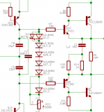
Bingo, i added a Shottky diode in place of NPN ThermalTrack diode, keep the 3 PNP diodes and 1 NPN diode.
1 NPN , 3 PNP, 1 Schottky on the heat sink near the hottest transistor, that's it. Lightly over-compensated (best for me because my heatsink are borderline). seems to work great.
1 NPN , 3 PNP, 1 Schottky on the heat sink near the hottest transistor, that's it. Lightly over-compensated (best for me because my heatsink are borderline). seems to work great.
Would someone be willing to show a quick sketch/schematic of this 'fix'. I want to understand it better before I try to implement it.
Thanks,
Ryan
Thanks,
Ryan
Bingo, i added a Shottky diode in place of NPN ThermalTrack diode, keep the 3 PNP diodes and 1 NPN diode.
1 NPN , 3 PNP, 1 Schottky on the heat sink near the hottest transistor, that's it. Lightly over-compensated (best for me because my heatsink are borderline). seems to work great.
I don't recommend the shottky modification unless you are prepeared to check properly that the tempco is close enough to correct with just 4 diodes left in place as the bias voltage generator.
I would much prefer to believe the designer when he/she says use 5 diodes for tempco.
I would much prefer to believe the designer when he/she says use 5 diodes for tempco.
Andrew: the BAT46 - Schottky diode has a negative temperature-coefficient as well and I recommend to fasten it on the heatsink.
When I built my prototype (having problems with the Vf of the internal TT-diodes), I did the following test:
I could not adjust the quiescent current / BIAS with 5 internal TT-diodes being active.
I could do the quiescent / BIAS adjustment with only 4 diodes being active.
I played music very loud for some time and then stopped playing. I could see that it takes a second or so, until the voltage that dropped
across 2 emitter resistors settled to the initial value that I adjusted during quiescent / BIAS adjustment.
I did the same test with the Schottky diode, bypassing the "5th" internal TT-diode.
After playing music for some time and then stopping it, the voltage that I measured across the 2 emitter diodes,
dropped to the initial value within the "blink of an eye".
This was the proof for me that the Schottky diode enhances the temperature compensation and is very near to the
originally designed "5 TT-diodes - solution".
In my current build, I use 5 internal TT-diodes and everything works as designed.
Best regards - Rudi
Last edited:
I have finally sorted out my problem mentioned in post 1244 (more than 2mA through the diode string). I think I must be getting too old and dopey for electronic projects as I failed to notice that LED D8 was not glowing! The reason was that it was installed back to front resulting in Q17 sourcing 5.9 mA instead of 1 mA.
For anyone experiencing biasing problems it would be worth checking the voltage drop across R17 in the current mirror. It should be around 0.33V when 2 mA is passing through the TT diodes.
Keith
For anyone experiencing biasing problems it would be worth checking the voltage drop across R17 in the current mirror. It should be around 0.33V when 2 mA is passing through the TT diodes.
Keith
Can anybody advise me, why my fronted PSU with 39V zener installed have on outputs 39 positive and 39.5 negative VDC? I have matched mje devices to 18% between each other.
I've tried different transformers with 34VAC and 38VAC on input of the PSU. According to published bom, zener has to be 36V type for 39V PSU (I want to have 42V PSU) or I understood something wrong?
I've tried different transformers with 34VAC and 38VAC on input of the PSU. According to published bom, zener has to be 36V type for 39V PSU (I want to have 42V PSU) or I understood something wrong?
Last edited:
measure the voltage across the zener diodes.
Then add on the two measurements you get for the series connected semis.
This total should be your output voltage.
I don't have the sch in front of me, Is this correct?
37 and 37.5 VDC on zeners and 39-39.5VDC on outputs.
Yes Andrew, this is correct, according to designer's ammendment, zener should be 36V type. Don't know that zeners shall be matched likewise.
I understand, thanks! Can they be matched?AndriyOL: "standard" ZENER diodes usually have a variation of 10%.
No reason to get worried.
Last edited:
These Zeners are operating at low current. Well under the 5% to 10% of current required for maximum power dissipation.
This results in lower than expected voltage across the Zeners. and also results in a bigger variation in voltage.
Your choice is take what you first pick up or select what you want/need from your stock.
400mW and 500mW Zeners cost about a cent/penny each when you buy 100.
Then you can select just about any value you want from the 100 on the band.
I strap a resistor to one the DMM probes.
Then apply +ve to one probe and -ve to the other probe.
Now go down the strip and read off the voltage at the current the resistor allows to flow. Write it on the paper strip.
These Zeners are operating at low current. Well under the 5% to 10% of current required for maximum power dissipation.
This results in lower than expected voltage across the Zeners. and also results in a bigger variation in voltage.
Any Zeners diode pakaged in less than 1W case and with Vr > 5v will be fully on reverse conduction for Ir >= 0.2...0.5 mA. There is no need for higher current trough a reverse polarized PN (or NP) silicone junction in order to have a true avalanche conduction and far away from the noisy corner of the reverse I/V curve
- Home
- Amplifiers
- Solid State
- RMI-FC100, a single stage audio power amplifier