Component woes!
I will admit that this project has gone way overtime in the build process, having purchased boards in the original group buy. In the past few days I have switched on one channel followed by the other a few days later.
In both cases no smoke, no drama and no instability, but biasing problems aplenty. I am using the NJL3281/1302 devices supplied by RS Components. The degree of matching was not good among the 10 of each device supplied, but that is not the whole storey. When first swiched on I had to bypass two thermal trak diodes to get the bias within range.
Originally I thought I may have been sold a faulty batch of devices, as it is well known that some early production thermal trak devices had the dies of the wrong diode installed in the device. However, on reading Rudi's experiences where he had to add a Schottky diode across one of the Ttraks as well as selecting the highest Vf Ttrak for bypassing; current thoughts are that I am up against a combination of "fudge factors"
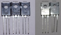
Perhaps the chief suspect is the quality of the Toshiba 2SA/2SC devices supplied by Crickelwood in the UK. The PNP 2SA1360's look the part with the notched cutouts around the mounting holes. But the NPN 2SC3423's have a very "plain Jane" package which may well be fake. I would be interested in comments on the appearance of these devices from others. None of the devices met the suffix Y hFE spec' and several of them simply didn't work.
When powering up the second channel no amount of Ttrak bypassing or adjustment turned on the OP devices. Found that Q19 (2SC3423) had no base emitter junction so replaced it. Its Vbe does not seem a particularly good match to its complement which is not helping the general biasing problems.
Anyone tried any successful substitutes for the Toshiba devices?
For the front end power supply I am using a single loop C core (two coil bobbins) on which I wound two new bifilar secondaries using 0.6mm wire. The regulation is way better than necessary as the core is possibly rated for 60VA or more.
Keith
I will admit that this project has gone way overtime in the build process, having purchased boards in the original group buy. In the past few days I have switched on one channel followed by the other a few days later.
In both cases no smoke, no drama and no instability, but biasing problems aplenty. I am using the NJL3281/1302 devices supplied by RS Components. The degree of matching was not good among the 10 of each device supplied, but that is not the whole storey. When first swiched on I had to bypass two thermal trak diodes to get the bias within range.
Originally I thought I may have been sold a faulty batch of devices, as it is well known that some early production thermal trak devices had the dies of the wrong diode installed in the device. However, on reading Rudi's experiences where he had to add a Schottky diode across one of the Ttraks as well as selecting the highest Vf Ttrak for bypassing; current thoughts are that I am up against a combination of "fudge factors"
Perhaps the chief suspect is the quality of the Toshiba 2SA/2SC devices supplied by Crickelwood in the UK. The PNP 2SA1360's look the part with the notched cutouts around the mounting holes. But the NPN 2SC3423's have a very "plain Jane" package which may well be fake. I would be interested in comments on the appearance of these devices from others. None of the devices met the suffix Y hFE spec' and several of them simply didn't work.
When powering up the second channel no amount of Ttrak bypassing or adjustment turned on the OP devices. Found that Q19 (2SC3423) had no base emitter junction so replaced it. Its Vbe does not seem a particularly good match to its complement which is not helping the general biasing problems.
Anyone tried any successful substitutes for the Toshiba devices?
For the front end power supply I am using a single loop C core (two coil bobbins) on which I wound two new bifilar secondaries using 0.6mm wire. The regulation is way better than necessary as the core is possibly rated for 60VA or more.
Keith
My 1360/3423 are in different To126 packages. These came from Dalbani.
Once you have working transistors in those positions, they will not affect the quiescent biasing. The Vf of the diodes determines the biasing.
You can control the current through the biasing diodes by pacing a resistor across each diode. Try a 3k across one diode and remeasure the bias current. That 3k should pass about 0.2mA That current is now not passing through the diode and thus the diode Vf drops a little. You can cary on adding one 3k to each diode in turn and measure the effect of each modification.
You may find that you can get the bias voltage you need with this simple mod.
Try to keep the 500r near the lower end of it's adjustment range.
I don't think you want 2mA passing through 400r to 500r for a 0.8V to 1V of bias voltage that is not temperature compensated. But that is for later once you have a bias current in the correct range (37mV to 38mV across a pair of emitter pins). I have a 1.2mV range from highest to lowest (37.8mV to 39mV) with my selected pairs.
Andrew, thanks for the mention of minimising pot R in the diode string. A bit analogous to "dead" capacitance in a condenser microphone or ES loudspeaker.
Maybe a question for Rudi_Ratlos. I thought it was agreed that when Iq of the driver transistors was raised by lowering R5 to 12R, C1 was unnecessary, yet Rudi's board seems to have resurrected it with that big pigtail component?
Keith
Maybe a question for Rudi_Ratlos. I thought it was agreed that when Iq of the driver transistors was raised by lowering R5 to 12R, C1 was unnecessary, yet Rudi's board seems to have resurrected it with that big pigtail component?
Keith
I have the exact same problem with my second FC-100. I have to short two ThermalTrack diodes to be able to adjust the bias and the thermal compensation is not correct, got thermal runaway.
I will try with 5 diodes and bypass them with some resistors to see. The PNP thermalTrack have a Vf of 0.44V and the NPN one 0.62V ???? Is it normal ??? didn't check the spec sheet.
I will try with 5 diodes and bypass them with some resistors to see. The PNP thermalTrack have a Vf of 0.44V and the NPN one 0.62V ???? Is it normal ??? didn't check the spec sheet.
Last edited:
Keith, the Vishay MKP1839 / 1µF was introduced by Mihai starting in post #345.
I currently know 2 "reliable" sources for authentic Toshiba 2SA1360/2SC3423 transistors: BD Enterprises and Pacificsemi.
I built my prototype using ISC 2SA1360 and 2SC3423, and they did their job very well!
I am using authentic Toshibas currently.
I had the "ThermalTrak Vf" - problem, when I built my prototype and used NJL0302/NJL0281 transistors that I bought several years ago.
When I did the 2nd round of the FC-100 group-buy, I bought several hundred of NJLs from MOUSER (current batch) and while matching them,
I also measured the Vf of the TT-diodes.
None (!) of the diodes had a Vf > 560mV at 5mA /25 degrees.
Best regards - Rudi_Ratlos
Attachments
Last edited:
that is suspiciously high @ 2mA................................a Vf of 0.44V and the NPN one 0.62V ???? Is it normal ???..........
Those NPN ones are the first I would add a resistor across. I would also take an NPN diode out of circuit so that you are using 3 low Vf and only 2 high Vf diodes in the string.
It may be that the NPN diodes will need a lower resistor value (to bypass more current) than the resistor fitted to the PNP.
If all the NPN diodes are Vf~600mV then a 680r resistor in parallel will bypass just under 1mA. The diode current is then just over 1mA. The Vf @ 1mA must be less than the Vf @ 2mA. Don't be surprised that the high Vf diodes need very low value resistors to get sensible bias voltage from the 5 diode string..
BTW.
I left all 5pin long on the top side of the PCB. I bent alternate in opposite directions to increase the gaps between adjacent pins. These long pins are now test points to attach clip on probes, or crocodile clips.
You can use these pins to clip across any diode to temporarily take it out of circuit. That then reduces bias voltage and bias current so that you can measure Vf when the sink is cold.
CAUTION !
Long PIN next to the fuse holder is very close. Be ultra careful you don't short Vdd to base PIN or Vee to diode PIN !!!!!!!!!!
Last edited:
Keith, the Vishay MKP1839 / 1µF was introduced by Mihai starting in post #345.=QUOTE]
Indeed it was, but at post 573 it is suggested that when the driver transistor Iq is raised to around 100mA C1 is no longer needed. Users of Rudi's boards will be able to keep their options open as the post 345 R and C was a pain to accomodate on the original board.
We need to be carefull with terminology when discussing bias voltages to discriminate between device Vbe's and thermal trak diode Vf's. I would have thought the thermal trak diodes would be the same for NPN and PNP devices and that if they are at the same temperature the Vf should be similar. DRZ1's thermal trak figures are way more divergent than any I have measured. What temperature/running time are these being measured at? Maybe we are looking at some faulty production from Onsemi. Can't recall where I heard about the faulty production but had the impression it was not NPN or PNP specific.
Rudi, thanks for your comments on the Toshiba devices. Seem to have lost the knack of using quotes on this forum. Select the text, hit quote, then what?
Keith
Last edited:
Andrew, I tried your idea of putting a shunt resistor across a thermal trak diode instead of shorting it out and it works very well. I had two diodes shorted, so I removed the short on one and put what I thought was a 3k3 resistor in its place. I wound the pot to zero ohms and switched on. Without touching a thing I have near optimum bias on that channel.
It turns out that the resistor is 33K, so it just needed the slightest voltage reduction in the string to bring it in range. The OP device Iq's stabilise faster than with two diodes shorted. Good suggestion.
Keith
PS So far I have not soldered a single thermal trak device in place as it would reqire a very specially shaped bit to unsolder them. I cut off lengths of tinned copper wire, flatten one end by squeezing it with pliers and force it into the via. Before doing so you need to get the flat end at 90 degrees to your pliers or what ever tool you are using to insert them. Often they will come to rest against the bend in the device lead below the board. I think the reliability comes from the square corners of the device leads contacting the inside of the vias. It is rather time consuming I will admit.
Last edited:
Roender found that adjusting the diode current he could alter the slope of the compensation with temperature, (at least that is what I remember of how I interpreted his reports).
He could use 4 or 5 or 6 diodes. Any of these could give the correct bias voltage simply by changing the diode string current.
He found that 2mA and 5diodes gave the best temperature compensation for his amplifiers with his transistors.
That does not mean that different diodes will always give the same result.
It appears that the 4 series of NJL have different diodes and that some from ONsemi may have had the wrong diode.
So some experimentation in diode current is probably advised, if tempco is not perfect.
Once the amp is up and running properly, at the desired Bias voltage/current, it is fairly easy to add different resistors, or no resistors, to see the effect on tempco.
What are the diode voltages? Is the 33k on the diode with the highest voltage? or another?
Depending on which you did, it may be prudent to add a resistor to another high Vf diode and dial in a little resistance with the 500r Vr.
Last edited:
And if i connect the pot in parallel with the diode string ?????
I think that this set up could work better than in series.
It upset me a bit because my first FC-100 work very well (super well compensated) with the exact same transistor (0302-0281) from an other batch.
I have tried it with NJL1302-3281 and it work very well too, but a prefer the sound with the first ones.
So friends wants a FC-100 too and wee purchased a pretty big batch of NJL and they seems to have a problem with this diode....
I don't have time to work on it this week, but i will give it some time next week.
Wait and see.
Denis
Last edited:
And if i connect the pot in parallel with the diode string ?????
I think that this set up could work better than in series.
It upset me a bit because my first FC-100 work very well (super well compensated) with the exact same transistor (0302-0281) from an other batch.
I have tried it with NJL1302-3281 and it work very well too, but a prefer the sound with the first ones.
So friends wants a FC-100 too and wee purchased a pretty big batch of NJL and they seems to have a problem with this diode....
I don't have time to work on it this week, but i will give it some time next week.
Wait and see.
Denis
Too bad that ONsemi f..ked up some production lots of NJLs. I'm convinced that they put by mistake other type of diode inside which requires other compensation current in order to correct track the transistor Vbe over temperature.
I do not recommend to bypass all the diodes string with the pot. Just use what Andrew recommend, one resistor over the diode with way out Vf than the others.
What are the diode voltages? Is the 33k on the diode with the highest voltage? or another?
Depending on which you did, it may be prudent to add a resistor to another high Vf diode and dial in a little resistance with the 500r Vr.
When running for around 10 minutes I am seeing Ttrak diode voltages of around 480mV. The one I shunted with the resistor was not selected as being higher than others, although I believe I have shorted the highest one.
By snipping through the resistor while powered the Vf came up just 1mV (477mV to 478 mV) I did not want to have the temperature change during the exercise. This is telling me that one diode shorted is almost enough to put the bias in range but it needs the slightest tweek to get it over the line. I will try a lower shunt R and some pot R.
Keith
Well, it's worse than i thought. At lightly warm temp NPN diode = 0.67V and PNP = 0.52V.
If i want about 2.5V total with 5 diodes i have to bypass too much current from the NPN diodes and they don't do their jobs ( i must put a 200 ohms across it to drop it to 0.5V).
I thought that the compensation diode was part of the transistor dye, so i'm surprised with an error like that.
any suggestions ? Schotky diode in place of them ?
Look bad....
Denis
Last edited:
Well, it's worse than i thought. At lightly warm temp NPN diode = 0.67V and PNP = 0.52V.
If i want about 2.5V total with 5 diodes i have to bypass too much current from the NPN diodes and they don't do their jobs ( i must put a 200 ohms across it to drop it to 0.5V).
I thought that the compensation diode was part of the transistor dye, so i'm surprised with an error like that.
any suggestions ? Schotky diode in place of them ?
Look bad....
Denis
No reason not try bypassing two diodes (2npn, 2pnp, or one of each). Or you might bypass two and use an external series diode of lower drop (on the heatsink) to get the correct voltage drop. You can play quickly by leaving all the diodes unbypassed, and just shorting them in different combinations with clip leads. One suggestion: Avoid bypassing the center device in the row of three. It will run a little hotter than the outer two, so will provide a little more compensation.
Sheldon
I have tried some of your suggestion, and it have under compensation if i use only 4 diodes.
I think the use of some external diodes will be the only solution.
The total voltage drop across the diode string, plus series pot, should be very close to 2.5V. As long as the series resistance required is lower than about 100R, then compensation should be adequate.
in my amp, the pot is set at about 50R. The diode string passes about 2mA, so that means the diodes drop about 2.4V total.
By my calculations you can get close to that with two NPN and two PNP diodes.
Sheldon
Too bad that ONsemi f..ked up some production lots of NJLs. I'm convinced that they put by mistake other type of diode inside which requires other compensation current in order to correct track the transistor Vbe over temperature.
I do not recommend to bypass all the diodes string with the pot. Just use what Andrew recommend, one resistor over the diode with way out Vf than the others.
When they were manufactured at the beginning, they did the same. It was good if I had read this, couple of weeks before. I would have dropped my RMI-FC100 project.
Now the thermaltrack order has already gone.
MAY GOD BLESS ME and I do not get these f.ke tranys.
Gajanan Phadte
- Home
- Amplifiers
- Solid State
- RMI-FC100, a single stage audio power amplifier