Yes, he did publish that. But later in the thread he said this;
So I took it that the MKII schematic was not a finished design. I don't have the knowledge or experience to finish it myselfl.
Sheldon
Sorry guys but this amplifier now incorporate some non-publicdomain ideas (AKSA) and I will not post in the net future development topologies based on this design. The results, good or bad sounding, will be non-commercial and non-publicdomain.
I strongly recommend you to build the original RMI-FC100, version with dual differential VAS, which is a great sounding amplifier, or to further develop around this single ended VAS topology.
Cheers
Mihai
So I took it that the MKII schematic was not a finished design. I don't have the knowledge or experience to finish it myselfl.
Sheldon

Sheldon,
Not quite - Mihai's design is complete, no question. I suggested a minor improvement to the output stage privately to him, and he found it gave small improvements, but aside from that, his design is completely finished and ready to roll.
Regards,
Hugh
Hello Mr. Hugh,
Would you be so kind to share this improvement with us, if it isn't shown in Mihai's MKII schematic.
Many thanks in advance.
Best regards.
Andriy.
Did you build RMI-FC100 MK II version or rebuild your first try?
In consideration of the information that followed my answer to this question; let me reconsider. I did in fact build another version I, with a more conventional layout than my first build. But, since I'm going to look for a better match of output devices on the one channel, and I have to do some component swapping anyway, I'm reconsidering the front end topology. I'm intrigued to try the single ended version -not because I'm in any way dissatisfied with the original, but just because it's a chance to try something a little different. It looks like it wouldn't be too difficult to modify a few traces to do it. I'd do it exactly as shown, unless there is reason to do otherwise. Sounds like it has Hugh's blessing and Chokey too. I'm game unless Mihai thinks it unwise.
Sheldon
edit: Actually, it looks like I wouldn't even have to modify any traces. A few components removed, a couple of free standing connections, and some jumpers. If I didn't like the results, easy to go back.;
Last edited:
I bought 100 ea of 2sa and 2sc semis. I will try to offer matched pairs of these when I can get around to matching them.
There's a group buy of the Toshiba 2SK170-V going on right now.
I'm very interested in those matched 2sa/2sc ones. Just ordered 100 2sk170-v. I might offer matched pairs too.
edit: Actually, it looks like I wouldn't even have to modify any traces. A few components removed, a couple of free standing connections, and some jumpers. If I didn't like the results, easy to go back.;[/QUOTE]
Looks like all I have to do is remove from the original schematic Q11,13, D2,7, R15,18, add appropriate jumpers, add R14, 15, 31,34(as shown on the MkII schema), and switch the drain and base on Q14. I don't need to cut any traces. But I do have a couple of questions for Mihai, or anyone who can answer them:
I assume that the change of C21 (feedback cap) from 470-330u is of no particular consequence?
C8,9 were changed from 15-22pf. Is this an important difference? Or is the ratio of R31,34 and C8,9 the important parameter?
Mihai suggested that at 100mA bias for the drivers, that C1 was not needed. The MKII schematic has it back in, with 0.8R in series. I take this as the preferred set up?
Finally, R19 changed from 91R to 96R. However, it looks like the current hasn't changed for the input bias string. R16,17 for the current mirror haven't changed, but it looks like the current there has changed (unless I'm adding thing up incorrectly - a distinct possiblity). Is the difference important?
Like I said, unless Mihai says otherwise, I'm game to try itl.
Sheldon
Attachments
Last edited:
Dear Roender
I have been reading this thread in the last couple of days, and I find it very interesting.
Please excuse my ignorance and stupid questions, but a couple of things puzzles me:
As far as I can see, if you use a device with a bigger die (like the NJL3281/NJL1302), the re of this device (assuming most of the re value comes from the die size and not internal leads aso) will be comparativly smaller. This again could lead to reducing the Re and you would end up the same B-biasing? A device with a die with double the current capacity would in my head equal two parralleled devices?? Am I missing somethig here?
The Cob would also be the same or less if you use fewer devices?
The other thing is the tempco issue. If you only use two output devices, you only have two internal diodes for tempco. But if you use a Vbe multiplier (the transistor NOT on heat sink) with the two diodes in series with the emitter, you would end up multiplying the tempco as well, so you end up the same place. Of course one set of NJL3281/NJL1302 will get sweat on their forehead , but this is only to make a point. You could probably get away with using two sets, haven´t done the calc. on that.
Hmm Maybe my questions are too stupid?
I can see a problem in the Vbe multiplier, as the Vbe multiplier transistors own Vbe will be multiplied as well and thereby reduce the influence of the Thermatec diodes, but what if you used an opamp to amplify 1 Thermatec diodes foreward drop five times. You would end up with the same result as a string of five Thermatec diodes in series, right? Of course the active devices has to share the load pretty much equally for this to work, but this amp uses matched devices.
Does any of this make any sense?
Koldby
Hi all,
Sorry for neglecting this tread, I am badly cached with may daily job and mare than that I was in a long trip in Himalaya")
I will answer your questions as soon as possible.
Sheldon, don't waste your time with the SE version of fc-100. Is very hard to tell if there is any improvements at all, at least on my MA Gold speakers. Maybe yours are more resolute and will cont.
Thanks,
Mihai
Sorry for neglecting this tread, I am badly cached with may daily job and mare than that I was in a long trip in Himalaya
I will answer your questions as soon as possible.
Sheldon, don't waste your time with the SE version of fc-100. Is very hard to tell if there is any improvements at all, at least on my MA Gold speakers. Maybe yours are more resolute and will cont.
Thanks,
Mihai


Greetings from Nepal
good luck , and have a fun !
Member
Joined 2009
Paid Member

http://magicalplacesoftheworld.files.wordpress.com/2009/05/mount-olympus3.jpg
Greetings Roender
Very happy to see you back_I am hoping for
news on the design or even just your thoughts
on it as to where it stands.
Hi all,
Sorry for neglecting this tread, I am badly cached with may daily job and mare than that I was in a long trip in Himalaya
I will answer your questions as soon as possible.
Sheldon, don't waste your time with the SE version of fc-100. Is very hard to tell if there is any improvements at all, at least on my MA Gold speakers. Maybe yours are more resolute and will cont.
Thanks,
Mihai
Thanks. Very nice pictures.
I was interested in the SE version, not because I expected better sound, but just because it was a chance to try something a little different. Mostly, it was an exercise in learning the amp a little better. But, I hate unsoldering stuff from a pc board, so maybe I'll just match my outputs better on the second version, and leave it at that.
Sheldon
Hmm Maybe my questions are too stupid?
I can see a problem in the Vbe multiplier, as the Vbe multiplier transistors own Vbe will be multiplied as well and thereby reduce the influence of the Thermatec diodes, but what if you used an opamp to amplify 1 Thermatec diodes foreward drop five times. You would end up with the same result as a string of five Thermatec diodes in series, right? Of course the active devices has to share the load pretty much equally for this to work, but this amp uses matched devices.
Does any of this make any sense?
Koldby
Koldby,
Could you please show me where you had seen a vbe multiplier transistor in RMI-FC100 topology?
Why complicate the schematics with a opaamp as a single tracking diode multiplier when we have access to all five TT diodes?
Keep it simple
Regards,
Mihai
This was actually a comment to my previous post in post 909, where I was wondering if you could use two pairs of NJL1xxx instead of 3 pairs of NJL0xxx and still get the right tempco.
Also I wondered ther if you couldn´t get the same class A bias along with the correct class B with a differen value Re..
Absolutely keep it simple, but if you can´t get the NJL0xxx, maybe a solution could be found with the same performance (Same total Cob )
Koldby
Also I wondered ther if you couldn´t get the same class A bias along with the correct class B with a differen value Re..
Absolutely keep it simple, but if you can´t get the NJL0xxx, maybe a solution could be found with the same performance (Same total Cob )
Koldby
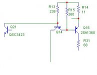
Mihai can I replace 2SC3423Y \ 2SA1360Y with 2SC2705Y \ 2SA1145Y? They are the same but in different package.
I can't find original 2SC3423Y \ 2SA1360Y transistors.
I guess if performance of SE version is no different from original, SE version is cheaper and simpler.
Regards.
I can't find original 2SC3423Y \ 2SA1360Y transistors.
I guess if performance of SE version is no different from original, SE version is cheaper and simpler.
Regards.
Last edited:
Mihai,
Thanks for sharing your good work. I have just been pointed to your amp so this must be it! I am looking for the best sounding class B / AB amp to drive my tweeter with my active speakers and I think this would be the best choice.
The trouble is that I have limited skills and at best could do it using perfboard and am not competent in matching devices, etc.
Are there PCBs, or better, kits available, which will save me a substantially amount of time and efforts and give me better chance of success?
Best regards,
Bill
Having built two of these, I would say that it's major overkill to use as a tweeter amp. Right now, I use the amp for 300Hz and up, just because that's the way my system is set up - and it's probably overkill there. As it was pointed out to me, the great advantage of this amp is that it can deliver clean power into complex loads, while delivering lots of current. You don't need that to drive a tweeter.
Of course it would work very well. But it's not an easy, or inexpensive amp to build. You don't need multiple paralleled output devices for any normal tweeter. And I certainly wouldn't try an amp of this complexity on perfboard.
I'd take a look at this one, as boards are available: http://www.diyaudio.com/forums/soli...symasym-pcb-design-rev_1-3-a.html#post1975505
Sheldon
Last edited:
- Home
- Amplifiers
- Solid State
- RMI-FC100, a single stage audio power amplifier