awhile back i posted about my setton BS-5500 amplifier.
it was clicking in and out of protect, so i checked inside and it had a pretty badly leaking power supply cap.
I changed all 4 caps 2 days ago, and soldered in new $20 ones with the correct values, correct way, etc etc etc.
I then measured dc-offset which was ~35mv a channel.
i even cranked it WAY UP for a while almost to clipping earlier today, and had no probs at all.
and then after letting it idle for about an hour, it started clicking in and out of protect again!!!!
what could be wrong??? i fixed one OBVIOUS problem, and now it's still not working?????
please help me with this !!!! i really appreciate it!!
thanks,
Henry
I just finished letting it cool down for about a half hour, and and then powered it up again and now it stayed out of protect for a couple minutes.
I am thinking that maybe:
1. it goes into protect more often when it's warm.
2. i may have been ruining a new cap by using it these past couple days--maybe something else is causing the cap to go bad, and when the cap starts to go bad, it goes into protect more often.
also, the amp does not run excessively hot or cool, so the bias current is probably not out of line.
I got your PM through AK, but since you started the thread here, here is where I'll answer.
First off, I know nothing about this amp. I wanna make that clear. But, if it uses some sort of a more or less conventional protection scheme, there is circuitry to mute the signal on power-up and power-down, and circuitry to monitor the output DC voltage as well. Circuits such as this generally control relays which interrupt the signal to the speakers when a fault condition is indicated.
You said something about the 'left' side going into and out of protect. Usually there is only one protection circuit for both stereo channels...if a problem is indicated on one channel, both channels are disconnected from the load [speakers]. If your amp has only one protection circuit, and you are losing only one channel, then the problem is not likely in this circuit.
Bottom line is I'd have to see some schematics before I made a more educated guess as to what the problem could be or to tell you where you might look. But if the amp has separate circuits and relays for each channel, it may be something as simple as some aging caps or weak transistor in this circuit.
EchoWars:
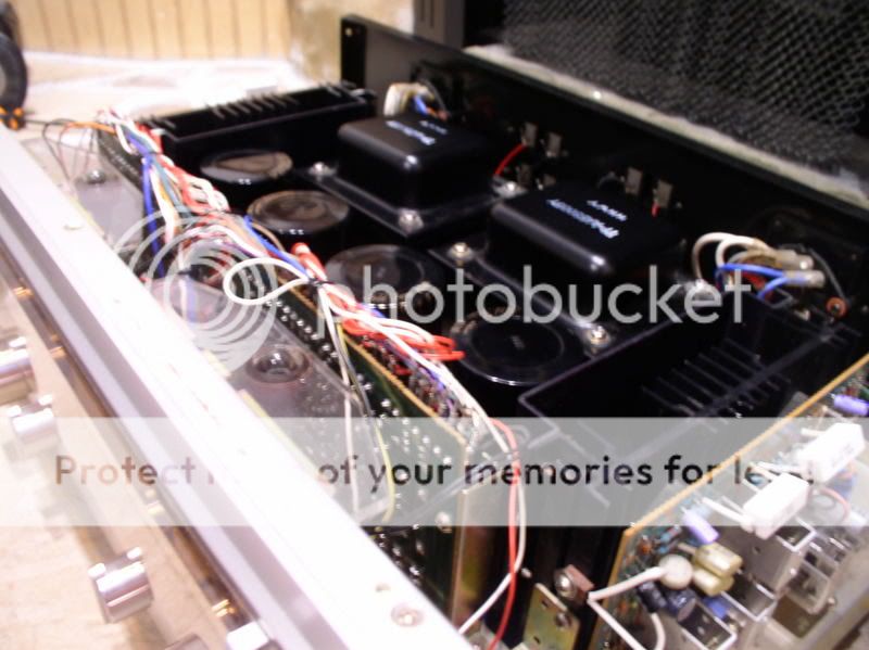
the BS-5500 has a true dual mono design, with a metal bar that runs down the middle of the amp entirely separating the two sides. thus, it has two power switches, two speaker selectors, two transformers, two protection circuits and relays, etc etc etc.
unfortunately, it is extremely rare--I have searched numerous audio forums, and asked just about everywhere to try to locate a service manual or schematic. I know of about 5 BS-5500 owners worldwide, a few are setton experts. even they do not know of a manual or schematic anywhere.
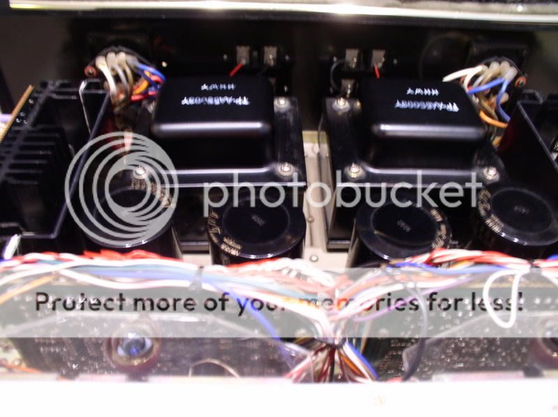
like sansui's it does have the "block diagram" printed on top of the case. I can post a pic of this if you want. amp nudies are below if that help at all.
let me know what you think i should do next!
also---I have 2 of these amps--the other works very well, but the offset measures 50mv/channel. after i changed the PS caps in the "broken" one, while it was working it sounded and worked much better than it ever had, and still proformed considerably better than the now only-working one(with 50mv/channel offset). but, even though it proforms so well, it clicks!
djk: i am certain that 35mv/channel would not cause the protection to engage. i had another pioneer amp (SX-939) that i used for years and the offset was always over 50mv/channel, and i never had a problem.
I do not have a clue what the timing capacitor should look like. below are pics--see if you can point it out so i can test it.
gmphadte: the amp is almost mint and i cannot see any solder problems or bad connections.
thanks for everyones help!!!
Henry
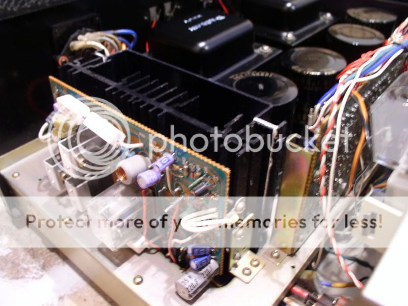
you can see the relay on the board in the second image. i would be happy to post more closeups if needed. also, the metal bar that separates them runs through on the underside, which i can also get a pic of if needed. there are no wires in common between the two sides on the top.
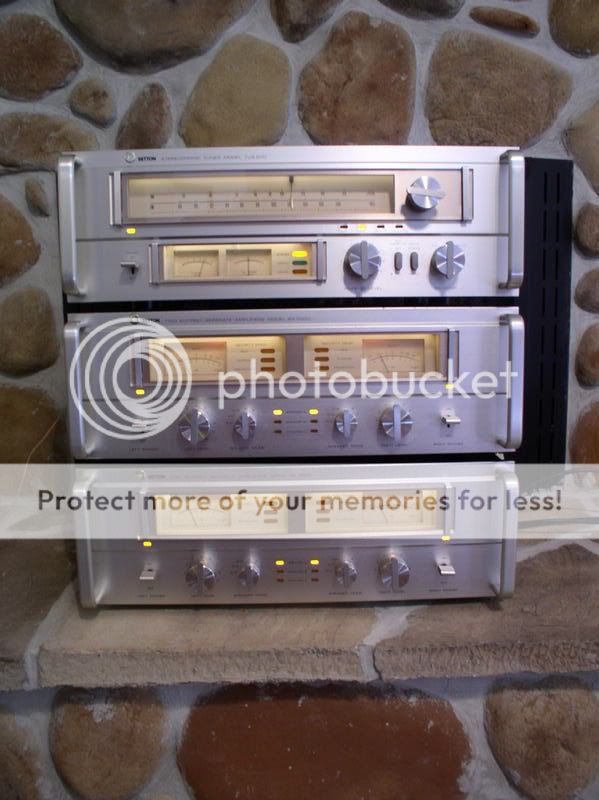
here is a pic of the two amps with a tuner on top when the amp worked:
the BS-5500 has a true dual mono design, with a metal bar that runs down the middle of the amp entirely separating the two sides. thus, it has two power switches, two speaker selectors, two transformers, two protection circuits and relays, etc etc etc.
unfortunately, it is extremely rare--I have searched numerous audio forums, and asked just about everywhere to try to locate a service manual or schematic. I know of about 5 BS-5500 owners worldwide, a few are setton experts. even they do not know of a manual or schematic anywhere.
like sansui's it does have the "block diagram" printed on top of the case. I can post a pic of this if you want. amp nudies are below if that help at all.
let me know what you think i should do next!
also---I have 2 of these amps--the other works very well, but the offset measures 50mv/channel. after i changed the PS caps in the "broken" one, while it was working it sounded and worked much better than it ever had, and still proformed considerably better than the now only-working one(with 50mv/channel offset). but, even though it proforms so well, it clicks!
djk: i am certain that 35mv/channel would not cause the protection to engage. i had another pioneer amp (SX-939) that i used for years and the offset was always over 50mv/channel, and i never had a problem.
I do not have a clue what the timing capacitor should look like. below are pics--see if you can point it out so i can test it.
gmphadte: the amp is almost mint and i cannot see any solder problems or bad connections.
thanks for everyones help!!!
Henry
you can see the relay on the board in the second image. i would be happy to post more closeups if needed. also, the metal bar that separates them runs through on the underside, which i can also get a pic of if needed. there are no wires in common between the two sides on the top.
here is a pic of the two amps with a tuner on top when the amp worked:
For some reason, my pictures do not seem to be working/linking to this page. Instead, a small red "x" appears where the picture is supposed to be. Do any of you know why?
Also. is there a way I can edit my posts? I forgot to spellcheck them and correct them like I'm supposed to, and the only one I that has the edit button is this one that I just posted.
Let me know!
Thanks!
Henry
Also. is there a way I can edit my posts? I forgot to spellcheck them and correct them like I'm supposed to, and the only one I that has the edit button is this one that I just posted.
Let me know!
Thanks!
Henry
Which would be both driver boards.
As regards DC, those had some double-die diodes similar to Marantz (IIRC), that would go open for very short periods. Hard to see without a storage 'scope. Replace the caps before looking further (advice from a former Setton service center).
As regards DC, those had some double-die diodes similar to Marantz (IIRC), that would go open for very short periods. Hard to see without a storage 'scope. Replace the caps before looking further (advice from a former Setton service center).
EchoWars said:Step #1: Recap the boards with the relays on them.
yes, sir!
should I do both sides, even the one that is working?
and, how about the boards that run perpendicular to the relay boards and parallel to the faceplate, if you know what I mean? I believe they have the DC-offset and bias pots on them. should I recap them too?
djk: what are double-die diodes? I do not really understand what you are saying--I am "technically challenged." Well, someday I will learn--I am only 16 and in highschool so I will have the opportunity someday.
Since I am not-so-good with the solder-iron, I have an older friend who helps me do it and he is showing me how--he goes by "rex everything" on the net--I think you know him, Glenn.
Buy enough parts for both channels, but concentrate on fixing the bad channel before you tackle the good one.
djk is talking about multijunction diodes. Used in current sources and amp biasing circuits. There's a dual-junction type out there that is simply a tiny 'bead', and they are terribly unreliable. Sony and Sansui used tons of them, and I replace them with two series 1N4148's. I don't think I'd sweat the diodes at the moment, as that's getting in a tad deep at this time.
If you can figure out which transistor acts as the driver for the relay, I'd replace it.
"is simply a tiny 'bead', and they are terribly unreliable"
That's what I'm talking about.
Usually when they start to go you will hear some popping sounds from the speakers when the relay trips.
Again, replace the caps first.
(caps are like cockroaches, you got to get 'em all)
That's what I'm talking about.
Usually when they start to go you will hear some popping sounds from the speakers when the relay trips.
Again, replace the caps first.
(caps are like cockroaches, you got to get 'em all)
Glenn: I think I will be able to find that relay transistor.
Setton also made a similar (and much more common) receiver, the RS-660. the RS-660 shares protection circuit/relay boards(I think they are similar, but i don't know for sure) and output transistors with the BS-5500. but the RS-660 is not dual mono design though. the other boards parallel with the faceplate on the BS-5500 have the dc-offset and bias pots on them--unfortunately, these are completely different from those on the RS-660.
the reason this matters is that I have access to an RS-660 service manual. but, the BS-5500 service manual is virtually unobtania--I have spent hours searching the web and asking setton collectors if they had one, or knew of anyone with one---but they don't. I have given up the idea of fixing it with the service manual.
so---would there be a way to adjust the offset and bias with out the manual????
thanks,
Henry
Offset is always zero (or at least desired), and may or may not be adjustable. Bias can be set if you can locate the:
a) Emitter resistors
b) Bias pot
Decide on a moderate idle current level (50mA or something), and calculate what you'll read across those emitter resistors.
As far as using another amp manual for this one, I suspect you're likely wasting your time. Get an eyeball on the back of the board with the relay, and follow the traces that go to the coil of the relay. You'll likely find they lead to the collector of the driver transistor and a power resistor (to soak up the excess voltage that the relay coil don't need). Probably at least a 1/2W resistor, maybe more.
I have found the relay coil. I will try to see where it goes, and mark the components you were talking about.
as for the pots: I just found that there is only one pot on the relay board, but 2 pots that are right next to each other on the board parallel with the faceplate. I suspect that the two next to each other are the bias and offset pots. but what's the other pot for???
how do I tell which is the offset and which is the bias??
I can post closeup pics of each of the boards if you want, and then blow them up so you can see them better.
thanks,!
Henry
- Status
- This old topic is closed. If you want to reopen this topic, contact a moderator using the "Report Post" button.
- Home
- Amplifiers
- Solid State
- amplifier clicking in and out of protection