

bobo1on1 said:Connecting the outputs of a 4 ohms stereo amp in parallel with two 0.5 ohm resistors might work, make sure you use resistors that can handle enough power.
The way you formulated the post can be misleading.
I am assuming you meant to connect a 0.5 ohm resistor in series with each 4-ohm capable amp output, then connect the two in parallel, and to the load. Inputs to the amps would go in parallel too, of course.
This should work (assuming one side of the amp outputs is common/ground), but will give a relatively high impedance for the source driving the sub, meaning the total Q of the driver + enclosure will be changed, most likely not for the better. Also a lot of power will be lost on the resistors.
Another way to do this would be to wind an impedance step-up autoformer, but it would be quite huge for the required low frequencies... possibly a 1kVA toroid core would be enough...
Many car Class-D audio amps are designed for these low impedance speakers and would be the cheapest solution.
Many of the big Krells will drive a 1.3 ohm speaker without damage. You might want to look for used KMA100s or KMA200.
If you want to DIY, you could build the Krell KSA 100 MKII clone designed here in diyAudio, and drop just the output power supply voltage to +/- 20V. Naturally a husky transformer and large filter caps are important.
Cheeze-ball table-top stereos have huge 'music power' ratings, but no real power (I used to design them).
What you do is have a passive crossover on the subwoofer, and wire the sub in series with the left and right speakers. The main speakers are so inefficient they need to lower the impedance of the sub to make the levels match. The grounds for the right and left speakers are tied together and connected to the hot lead of the sub, and the other lead of the sub is returned to the common ground. A capacitor is wire in parallel with the sub (the crossover).
What you do is have a passive crossover on the subwoofer, and wire the sub in series with the left and right speakers. The main speakers are so inefficient they need to lower the impedance of the sub to make the levels match. The grounds for the right and left speakers are tied together and connected to the hot lead of the sub, and the other lead of the sub is returned to the common ground. A capacitor is wire in parallel with the sub (the crossover).
djk said:Cheeze-ball table-top stereos have huge 'music power' ratings, but no real power (I used to design them).
What you do is have a passive crossover on the subwoofer, and wire the sub in series with the left and right speakers. The main speakers are so inefficient they need to lower the impedance of the sub to make the levels match. The grounds for the right and left speakers are tied together and connected to the hot lead of the sub, and the other lead of the sub is returned to the common ground. A capacitor is wire in parallel with the sub (the crossover).
What he said. The system indicates only one amplifier to drive this stuff. I wouldn't be surprised if the subwoofer being talked about has 2 voice coils, one to be driven by each stereo section.
Powertimes, what are you going to use this with? Unless it's with a similar type of system I suspect you won't enjoy it very much. I think it'll run out of puff well before any of your other speakers.
You could probably use it with one of those old NAD 3020 amps that you can pick up fairly cheaply off the 'bay - they were rated 20w/8, 35w/4, 70w/2 and can probably do the 1.3 unless you drive them really hard.
First off, the 100W is peak power, not RMS.
Two sections of the LM4780 chip-amps paralleled will drive it quite well. National Semiconductor recommends using a 0R1/3W resistor on the output of each section of the LM4780 for parallel operation. A paralleled LM4780 would be capable of 120W peak power. Application note at the link.
http://cache.national.com/ds/LM/LM4780.pdf
130W peak into 1R3 requires about 16V peak, or 12.4A peak. Looking at the data sheet we see that we are OK for two paralled sections.
You will need a transformer in the range of 24VCT~28VCT at 4A with a 25A bridge rectifier and a pair of about 15,000µF/25V caps.
While this could be done, I would buy a different driver and use an off-the-shelf plate amp.
"I wouldn't be surprised if the subwoofer being talked about has 2 voice coils, one to be driven by each stereo section."
Two voice coils mean twice as many connections to be made, and twice as many parts in the crossover. Why would they do that when they only need one voice coil?
unclejed613 said:you could also use an amp rated at 500W/4 ohms, and only drive it to 100W/ 1.3 ohms. the "overpower" amp would certainly have enough current capability, but it's up to you to limit the peak voltage to 11.5Vrms.
That was my though also, but the temptation to "crank it" is too enticing. Better to sell it, and let someone else blow up their amp or this sub.
")
unclejed613 said:you could also use an amp rated at 500W/4 ohms, and only drive it to 100W/ 1.3 ohms. the "overpower" amp would certainly have enough current capability, but it's up to you to limit the peak voltage to 11.5Vrms.
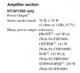
Guys, this is a low-end driver from a 5.1 Sony package HT system. Originally, it was probably powered by a 70W chip. Specs list the system as 28-20,000Hz, which could be -3dB, -6dB or -10dB (international system of mystery
).Simply using your multimeter to see what the Re of the speaker is might give a bit more of an indication of what the speaker actually needs - I doubt it would be 1.3 ohms when you measure it. My guess is around 3.5 ohms.
There are some "budget" home theatre systems available that uses low impedance speakers to obtain relatively high power from low voltage PSU.
This not bad or good, if the amplifier is designed to drive low impedances then it could work as well as any other system. I know Bose had speakers of <2 ohms around the early eighties.
There was another bunch of guys, that Jan may recall; Servo Sound (from Denmark) in the early seveties with what was probably the first commercial active loudspeaker system in the world. They used several smaller 3 ohm loudspeakers in parallel per box - probably a forerunner of the Bose idea.
It is not at all impossible to design an amplifier specific for an aplication. You start with a requirement specifying the result and work from there.
- Status
- This old topic is closed. If you want to reopen this topic, contact a moderator using the "Report Post" button.
- Home
- Amplifiers
- Solid State
- 100w into 1.3ohms